


 Espanhol (pdf)
 Artigo em XML
 Referências do artigo
 Enviar este artigo por email
 Citado por SciELO
  Citado por Google
  Similares em
SciELO
Similares em
SciELO  Similares em Google
 Permalink
1. INTRODUCTION
1.1. Bone repair
Bone repair is a complex process consisting of a cascade of osteogenic events. After an injury, different cell types, signaling molecules, and matrix proteins work together to repair the bone defect. However, the natural mechanism of bone healing is inadequate for large bone defects which cannot be treated with routine clinical procedures [1].
Bone defect reconstruction has conventionally been based on the use of autologous bone grafts or autografts. They are considered the gold standard and the most effective method for bone healing and regeneration because they provide osteogenic cells and essential osteoinductive growth factors. In addition, they offer relatively better chances of success, as they do not cause an immune response. However, some of their limitations include the need to remove bone from another part of the body, an increased morbidity of the donor site, costs associated with surgeries, and a longer recovery time [2].
Allografts (tissues extracted from another person's body) and xenografts (tissues extracted from animals) are also widely employed in bone repair.
Nevertheless, they may induce immunological rejection and transmission of pathogens from the donor to the host [3]. Some of the materials commonly used as substitutes for bone grafts include metals and ceramics. Although metals offer immediate mechanical support at the defect site, they poorly integrate with the host tissue and can fail due to fatigue loading. Ceramics are brittle, have low tensile strength, and cannot be used in defects located in areas subjected to torsion, bending, or significant shear stress [4].
1.2. Bone tissue engineering
To overcome the limitations of current graft procedures, new alternative therapies have been introduced, such as bone tissue engineering. This approach provides a reliable, affordable, and physiologically acceptable solution for bone regeneration. The term “tissue engineering” proposed in 1993 refers to a field that combines materials engineering with biology to produce Three-Dimensional (3D) scaffolds that mimic the Extracellular Matrix (EMC) and the functionality of natural tissue [1], [2].
Bone Tissue Engineering (BTE) has been regarded as an alternative to regenerate critical bone defects. It aims to create 3D bone tissues, as from graft substitutes or scaffolds, using in vitro seeded cells (e.g., Mesenchymal Stem Cells-MSCs-and Endothelial Progenitor Cells-EPCs-), as well as bioactive molecules, such as growth factors [1], [2].
1.3. Bone tissue requirements
For the bone system, scaffolding is required to enable a much firmer structural support (i.e., mechanical resistance) due to the physical loads that bones must support. Other relevant requirements for BTE scaffolds include:
Bioabsorbability [6]
Slow biodegradability [5]
Angiogenesis [6]
Porosity and microarchitecture that mimic the extracellular matrix (EMC) [5]+, [8]-[11]
Osteoconductivity and osteoinductivity [12] -[17]
Surface properties [8], [18]-[20]
Suitable mechanical strength [8]
In BTE, different techniques have been implemented to develop scaffolds, including gas foaming, fiber meshes sintering, solvent casting, polymerization in solution, porogen leaching method, freeze-drying, 3D printing, and electrospinning. This latter method has become popular because it mimics the nanoscale properties of the native EMC, thus promoting cell growth.
Silk Fibroin (SF) has been commonly employed in wound dressings and drug delivery applications. However, its use in bone tissue engineering has been little explored.
This paper presents an overview of the potential use of SF with electrospinning for bone tissue regeneration, as well as the physicochemical characterizations of electrospun silk fibroin scaffolds such as their morphology (via Scanning Electron Microscopic-SEM-), crystalline structure (via Fourier Transform Infrared-FTIR-spectroscopy and X-Ray Diffraction-XRD-), thermal characteristics (via Differential Scanning Calorimetry-DSC-and Thermogravimetric Analysis -TGA-), and mechanical properties (tensile strength). In addition, we discuss the potential applications and impacts of electrospun silk fibroin in bone tissue engineering and future research trends.
2. ELECTROSPINNING
With this technique, nanostructured membranes containing nanofibers with diameters below 500 nm are produced.
Moreover, it serves to fabricate scaffolds using micro/nanofibers. Their high porosity, morphology similar to that of a natural EMC, high surface area to volume ratio, and small interconnected fibrous pores promote cell adhesion, migration, and proliferation, thus creating new bone tissue.
Electrospinning has proven to be simple, versatile, cost-effective, and reproducible [24]. It uses an electric field to convert polymer solutions into fiber forms [25]. This process consists of three main components: (1) a high voltage source, which guarantees a continuous electric field with a positive and a negative polarity; (2) an infusion pump, adjusted to control the feed rate of the polymer solution contained in a syringe with an inner capillary diameter of 0.1-1 mm or needle; and (3) a metallic collector (usually a stationary aluminum plate or a rotating cylinder) where the resulting fibers are deposited [26].
To achieve fiber deposition, the solution must be exposed to a voltage between 10 and 50 kV. This voltage is applied between a suspended drop of the polymer solution located at the tip of the needle nozzle and a grounded stationary or rotating metallic collector that serves as a counter-electrode. Electrospinning is performed by controlling the temperature and humidity.
When the applied electric field exceeds the surface tension of the droplet, a conical shape (Taylor’s cone) is formed, and a charged jet of the polymer solution is ejected during the elongation and instability phase. Such jet is drawn by the electric field to the collector located between 10 and 25 cm away from the needle. The jet becomes long and stable, forming thin filaments, while the solvent evaporates quickly. Finally, the Two-Dimensional (2D) nanofibers are deposited in the grounded collector; or the 3D nanofibers, in the methanol colloidal solution [25].
Although the shape of electrospun nanostructured membranes has been limited to a 2D sheet form, recent works have proposed the construction of sponge-like 3D scaffolds. This 3D scaffolds have proven to be highly efficient for cell attachment during the former stages of cell culture. This, along with their highly porous structure, is beneficial for the exchange of nutrients or gases between cells [27].
The electrospinning process is influenced by several factors, including the solution’s properties (polymer concentration, viscosity, electrical conductivity, surface tension, and dielectric characteristics), processing parameters (voltage, flow rate, distance between the needle and the collector), and environmental conditions (humidity and temperature). In order to avoid the presence of droplet defects and allow a proper fiber formation and structuring, such factors should be controlled [24], [28].
2.1. Silk Fibroin
Silk Fibroin (SF) is a natural fibrous protein that is extracted from the cocoon of silkworms. It has been employed to produce a variety of biomaterials (e.g., gels, sponges, membranes, and films) for biomedical applications [29]-[34].
Its use has been explored in drug delivery and tissue engineering. For instance, it has been employed as a cell culture substrate due to its suitable biocompatibility, slow biodegradability rate, microbial resistance, low inflammatory response, good cellular response, and good oxygen and water vapor permeability and moisture [30].
However, SF is brittle, so it can easily break in a dry state, but combining it with other polymers can improve its mechanical properties [35]. Moreover, SF nanofibers have low osteoinductive properties; hence, a wide range of osteogenic agents have been incorporated to improve cell-matrix interactions and osteogenicity, making it a suitable biomaterial for bone tissue engineering [35].
The fibrous structure of SF is similar to that of type I collagen (Col I). Its amorphous bonds between the ( sheets serve as sites for the deposition of hydroxyapatite nanocrystals because they can mimic the anionic structure of Non-Collagenous Proteins (NCPs). The inherent integrin-binding tripeptide, Arg-Gly-Asp (RGD), present in the amino acids enables firm cell adhesion in fibroin obtained from the cocoons of non-Morera species (Bombyx mori) (e.g., Tussak or Samia Cynthia ricini) [30]. The maximum tensile strength of fibroin extracted from Bombyx mori ranges from 300 to 740 MPa.
In addition, such fibroin has a higher resistance to breaking than synthetic fibers, such as Kevlar [2]. These two factors are important values for bone tissue applications.
Fibroin is extracted by cutting the cocoons into small pieces which are dissolved in distilled water and 0.2 % sodium carbonate (Na2CO3) at a temperature of 80 °C [36]. Then, they are rinsed with distilled water to remove impurities. The degummed SF fibers are dissolved in a ternary solvent system consisting of calcium chloride (CaCl2) / distilled water (H2O) / ethanol (CH3CH2OH) (molar ratio = 1: 8: 2) or in 9.3 M lithium bromide (LiBr) at 60 °C for 1 hour. This solution is dialyzed using tubular cellulose membrane (12 kDa, Sigma Aldrich) (MWCO: 12,000-14,000 Da) with distilled water at room temperature for 3 days to eliminate salts (CaCl2) or to remove the remainder LiBr and then stored in a refrigerator at 4 °C for its conservation [37].
The use of caustic and organic solvents potentially compromises the biocompatibility and mechanical properties of silk fibroin fibers [38].
Therefore, solvents for dissolving silk fibroin should not interfere with the biocompatibility of the processed material when exposed to cells in vitro or in vivo [39]. The secondary structure of silk fibroin ((-sheets) in the electrospun fibers must be maintained to achieve optimal mechanical properties [39]. Employing forced winding directly from silkworms or a hot aqueous ammonium sulfate coagulation bath, produces fibers with exceptional mechanical properties. The most desirable approach would be to exactly mimic the natural process, where water is the only solvent [40].
2.2. Silk fibroin solution
In general, high concentrations of silk fibroin or adding other polymers, such as Polyethylene Oxide (PEO), is required to generate silk fibroin nanofibers from a silk fibroin solution during electrospinning [41]. The following solvents have been widely used to prepare silk fibroin solutions for electrospinning:
Fibroin lyophilized in 98 % formic acid [27], [39], [41]-[48] at concentrations from 5 % wt to 20% wt; distilled water with Polyethylene Glycol (PEG) [40], [49]-[51] at concentrations of 10 % wt PEG and 30-40 % wt SF; or PEO [38], [39], [50]-[56] to achieve electrospinning at concentrations of 5 % wt PEO and 9 % wt SF. Silk fibroin lyophilized in formic acid produces thinner nanofibers than PEO. When compared to distilled water, formic acid is found to increase the intramolecular hydrogen bond by enhancing (-sheet crystallization and minimizing the hydrodynamic radius of fibroin. However, the use of formic acid, for instance, could lead to cytotoxicity and an immune response [57]; PEO may affect the mechanical properties and biocompatibility of the fibers [39]; and Hexafluoroacetone (HFA) hydrate [58], at concentrations from 2 % wt to 10 % wt, could also compromise the biocompatibility of the fibers [39].
2.3. Electrospinning parameters for fibroin
Some studies have defined the following electrospinning parameters for silk fibroin: flow rate of 0.5 mL/h [59], voltage of 15 kV [53], [59], and a distance of 15 cm between the needle and the collector [60]. The most widely employed collectors are rotating drum, flat sheet of aluminum foil, and spinneret submerged in a methanol bath. Electrospinning is carried out at room temperature and a relative humidity of 40-60 %. To obtain the membranes, subsequent treatments have also been reported, including cross-linking, which induces structural conformational changes and crystallization of amorphous sheets into (-sheets.
3. PHYSICOCHEMICAL CHARACTERIZATION OF SILK FIBROIN NANOFIBERS
3.1. Morphological analysis - Scanning Electron Microscopy (SEM)
The morphology of electrospun SF nanofibers was analyzed using SEM at a temperature of 20 °C and a relative humidity of 60 %. The samples were mounted on a copper plate and cathodically sprayed with a 20-30-nm-thick gold layer before obtaining the micrographs [41]. The acceleration voltage was set between 10 and 20 kV, and approximately 50 random fibers were measured to determine the average fiber diameter and its distribution by means of the following image analysis software: Image J [50], [54], [61], [62], Inner View TM [45], and SemAphore 4.0 [42].
The higher the concentration of fibroin, the larger the average diameter of the nanofibers: 6 % wt: 53.9 nm [41], while 33 % wt: 1602 nm [38]. Fig. 1, shows the increased diameter of the nanofibers of pure SF (from 146.58 ± 36.09 nm to 262.21 ± 77.55 nm) due to coagulation time with methanol. This might be caused by an increase in the composition of the (-sheet, which, in turn, leads to a higher interaction between the chains and, thus, the formation of larger fibers [38].
Treatment with methanol induces a higher dispersion in the average diameter of the nanofibers, as observed in the histograms.
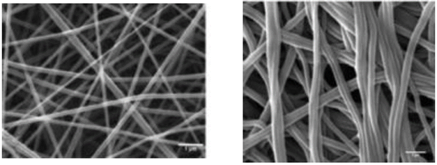
Source: [47]
Fig. 1 Silk Fibroin (SF) nanofibers at concentrations of 13% wt. (a) Pure SF 146.58 ± 36.09nm, (b) Cross-linked SF in methanol bath 262.21 ± 77.55nm
3.2 Crystalline structure - Fourier Transform infrared (FTIR) spectroscopy
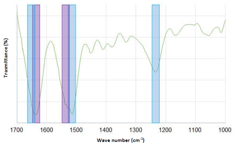
FTIR spectroscopy was used to determine the chemical composition of silk fibroin nanofibers via an Attenuated Total Reflectance (ATR) accessory. For each measurement, 128 scans were coded with a resolution of 4 cm-1, with a spectral region ranging from 400 to 4000 cm-1 [41], [47], [50], [57], [63], [64]. Curve-fitting and deconvolution methods were applied to the most informative fibroin region of amide I and amide II extending from 1750 to 1450 cm-1 and associated with the secondary structural conformation of α-helix and (-sheet. In addition, the spectra were analyzed using OriginPro [45], [65], PeakFit v4.12 [66], [67], and Spectrum [64].
FTIR spectroscopy was employed to examine the conformational changes that occur during the electrospinning process.
The α-helix showed strong absorption bands at 1656 cm-1 (amide I) (C=O stretching vibrations), 1540 cm-1 (amide II) (secondary N-H bending), and 1230 cm-1 (amide III) (C-N stretching vibrations and N-H bending). The estimated percentage of (-sheets was 29.28 %. Both crystalline and amorphous structures coexisted in different proportions in the silk fibroin samples, and a greater presence of β-sheet structures in the nanofibers was observed [43], [57], [65]-[68]. The absorption bands moved slightly after treatment with methanol or ethanol to 1626 cm-1 (amide I), 1523 cm-1 (amide II), and 1260 cm-1 (amide III), which indicates that the structure changed to crystalline (-sheet monoclinic antiparallel chains pleated in the electrospun nanofibers [50], [54], [63] .
This is a critical factor for the low in vivo biodegradability of silk-based materials. However, their crystallinity is very low compared to that of the raw silk fiber [41], [45], [47], [64]. Fig. 2 presents the FTIR spectra.
3.3 Crystalline structure - X-Ray Diffraction (XRD)
The crystal structure of silk fibroin nanofibers was studied using an X-ray diffractometer with a LynxEye detector [67], a CuKα radiation source (wavelength λ = 0.1541 nm) operating at 40kV and 40 mA over diffraction angles measured from 2θ = 0-40 °, and an X'celerator counter [49], [69] at a scanning rate of 0.015 °/s [67], 0.040 °/s [49], 0.048 °/s [70]. These parameters serve to obtain an X-ray diffractogram [71].The crystallinity of the silk fibroin nanofibers and the variation in the percentage of (-sheet content corresponding to the crystal structure due to enzymatic degradation were determined [49]. The database of the International Centre for Diffraction Data (ICDD) was employed to identify the composition of the phase [64].
Fig. 3 shows the XRD analyzes of the silk fibroin nanofiber membranes that were cross-linked in methanol or ethanol-solvents that induce crystallization. In such figure, diffraction peaks at 2θ = 14.51 °, as well as less intense peaks at 2θ = 20.74 ° and 2θ = 23.9 °, are observed.
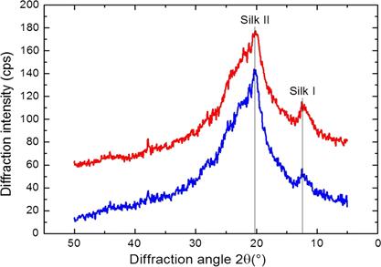
These peaks are characteristic of the silk II structure and confirm the existence of β-sheet structures [49], [67], [69] of 10.1 Å ([100+ 010 + 001] reticular plane), 4.4 Å ([200 + 020] reticular plane), and 3.7 Å ([201] reticular plane) of diameter. In addition, these peaks indicate the coexistence of crystalline and amorphous structures in the electrospun of silk fibroin nanofibers although they were treated with methanol [69]. The estimated percentage of crystallinity of the pure silk fibroin membrane was 22.24 % [47]; its increase (to 35.54 %) is attributed to methanol [47], [66], [70], [72].
3.4 Thermal analysis - Differential Scanning Calorimetry (DSC)
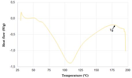
Samples weighing 5 mg were encapsulated in a sealed aluminum tray and heated in a differential scanning calorimeter under a dry nitrogen gas flow of 50-100 mL/min and at a heating rate of 10 °C/min and temperature ranges of 30-300 °C.
Fig. 4 shows the DSC thermogram of silk fibroin. According to this figure, there is an endothermic peak at approximately 80-100 °C, which is associated with water evaporation. The appearance of another endothermic peak at 180 °C for the compounds is caused by the start of the crystallization process within the silk fibroin (silk I and silk II). The occurrence of another peak at 278 °C is attributed to the thermal degradation of amorphous silk fibroin, a behavior related to the fact that unstable noncrystalline structures can be transformed into crystalline structures of the β-sheet [65], [68], [73]-[76]. Finally, the strongest peak around 360 °C is due to the melting and decomposition of the silk fibroin, which corresponds to its semi-crystallinity [30].
3.5 Thermal analysis - Thermogravimetric Analysis (TGA)
Prior to this analysis, all samples were stored in a container with silica gel to eliminate the effect of water. The thermal properties of 2 mg of each sample were characterized using a thermogravimetric analyzer under a nitrogen atmosphere with a gas flow of 20-100 mL/min- Then, they were heated at temperature ranges of 25-1800 ° C and at a heating rate of 10 °C/min. Measurements were determined based on temperature increase in order to evaluate the thermal degradation behavior of the samples.
The curves were divided into two regions. Region I recorded a weight loss of around 7 % (attributed to water evaporation) at 100 °C [62] with respect to the original sample, while region II exhibited a weight loss of 20 % at 270-370 °C. This is linked to the thermal degradation of silk fibroin, which is, in turn, associated with the decomposition of peptide bonds of amides [65].
Fig. 5 illustrates the weight variation of the silk fibroin nanofibers. When temperature increased to 350 °C, their original weight reduced approximately by 50 %. At 600 °C, their weight residue was around 9% and 11 % [77]. Their thermal degradation was significantly higher compared to that of composite nanofibers (97.246 % for pure fibroin and 92.268 % for silk fibroin / reduced Graphene Oxide RGO nanofibers) [78]. The silk fibroin scaffold and Hydroxyapatite (HA) exhibited better thermal stability, with a weight loss of approximately 30-35 % at 375 °C [62], [79].
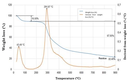
This analysis shows that scaffold treated with ethanol can better withstand higher temperatures than untreated samples because treatment with ethanol increases the structural crystallinity of the (-sheet form of silk fibroin, making it more thermally stable [49], [70], [71], [81], [82].
3.6 Mechanical properties - Tensile Strength (TS)
This procedure consists in the application of longitudinal force to a rectangular test piece, in accordance with the ASTM D882 or ASTM D638 type V standards. Tissue engineering scaffolds must possess a high tensile strength which is an essential factor since it supports cell growth in vitro and tissue organization. In addition, they must have the desired elastic modulus to facilitate the osteogenic differentiation of the cells [49]. Also, the alignment of silk fibroin nanofibers can also improve the required mechanical properties. Fig. 6 depicts the stress-strain curve of a electrospun randomly oriented silk fibroin scaffold (concentration of 15 % wt) with a maximum tensile strength of 7.25 MPa and a Young's modulus of 515 MPa [43].
Source: [43]
Fig. 6 Stress-strain curve of electrospun randomly oriented silk scaffold at a concentration of 15 %wt
This mechanical property allows the successful retention of Mesenchymal Stem Cells (MSCs), an aspect of great importance for tissue engineering because scaffolds should ideally maintain their shape during implantation and withstand mechanical loads after implantation [49].
The samples were carefully removed from the foil and cut into strips with the following sizes (length x width): 3 mm x 3 mm [83]; 0.5 cm x 4 cm [43], [53], [56]; 50 mm x 5 mm [41], [69]; and 50 mm x 12 mm with a thickness of 0.30 mm ± 0.01 mm [49]; 30 mm x 10 mm with a thickness of 0.8 mm [52], [64]; and 10 mm x 50 mm [66], [70], [74], [78] with a thickness of 0,16 mm ± 0,01 mm [70], (60 ~ 110 μm) [66], (170-370 nm) [74].
Then, they were pasted on a square paper template and tested in a universal machine at room temperature and a relative humidity of 65% using a load cell of 10 N at a constant extension rate of 20 mm/min [43], [49], [60], [74], [83], [84]; 5 mm/min [69], [76]; 10 mm/min [53], [66], [74]; and 50 mm/min [85]. The gauge length was 20 mm [66], [84]. The maximum tensile strength (MPa), Young's modulus (MPa), and elongation percentage (%) were determined based on the recorded force-elongation curve [37], [52], [53], [60], [64], [74], [76], [78], [84]-[86].
An average of five measurements was taken as the mean ± standard deviation for each sample [41], [66].
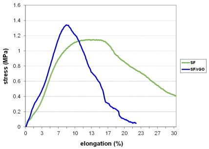
The increased tensile strength of silk fibroin scaffolds treated with ethanol or methanol could be attributed to a higher fiber crystallinity. The crystalline structure of the (-sheets and the compactness of the scaffolds may be responsible for the reduced elongation at the time of failure [37], [70], [78]. The elongation at break decreased after the incorporation of the carbon nanotubes.
The composite nanofibers were less flexible compared to the pure silk fibroin nanofibers. However, it led to a higher maximum tensile strength and Young's modulus [86].
The tensile strength, the deformation percentage, and the Young's modulus increased with the increasing HA content up to 20 % wt. Nevertheless, they decreased after that because the HA nanoparticles tend to aggregate when their density reaches a critical level. As a result, the fibers can turn discontinuous and brittle. Therefore, large quantities of HA could accelerate the breakage of the scaffolds during the tensile test [60], [74].
Silk fibroin membranes containing 0.5 % wt of rGO treated with methanol showed higher values of percent strain, and those containing 3 % wt reported an improved maximum fracture strength.
This latter is caused by the intermolecular forces formed between SF and graphene, which restricted the movement of the polymer chains [78].
The variations in silk fibroin concentrations from 0.8 % wt to 41 % wt result in a higher maximum tensile strength (0,3-10 MPa), Young's modulus (0.3-515 MPa), and deformation percentage (4 %-250 %). However, since the reported works used different measurements to test the specimens, the obtained results cannot be compared.
4. CONCLUSIONS, DISCUSSION, AND FUTURE WORK
Bone tissue engineering has a global impact on bone replacement and repair [10], which is why it constitutes one of the most active research areas in the field of tissue engineering. One of the greatest challenges in developing scaffolding materials concerns the suitable combination between properties such as mechanical strength and biodegradability.
In fact, these two latter behave antagonistically. Although, on the one hand, metals, apatites, and crystalline polymers show great mechanical strength, they are not biodegradable. On the other hand, amorphous apatites and bioglasses lack mechanical strength but exhibit good biodegradability. This evidently becomes a dilemma when developing new materials for bone tissue engineering [5].
Scaffolds must be able to adapt to the implantation site. Therefore, it is necessary to move from in vitro research to in vivo tests. In this regard, we highlight the efforts made in various studies to develop functional and affordable bone substitutes, for example, through the manufacture of polymeric or ceramic scaffolds using nuclear magnetic resonance images, considering the anatomy of the patient [10].
The solutions employed in silk fibroin electrospinning have an effect on the morphology of nanofibers. For instance, 98% formic acid-the most widely used solvent-increases the crystallization of β-sheets and reduces their hydrodynamic properties [43].
For the successful development of scaffolds, the proper electrospinning parameters (e.g., flow rate and voltage) should be determined to generate fibers without droplet defects. Morphological characterization using SEM serves to analyze the average diameters of the nanofibers, which vary depending on the concentration of silk fibroin (6 % wt = 53.9 nm and 33 % wt = 1602 nm). Moreover, scaffolds treated with ethanol and methanol exhibited a higher surface structural stability [70].
Porosity is another important factor in bone tissue engineering. The minimum required pore size is ∼100 μm to enable cell migration and infiltration into the scaffold. Nevertheless, pore sizes greater than 300 μm are recommended to allow new bone formation [87].
According to the XRD analysis conducted, the crystallinity of silk fibroin was not altered by the electrospinning process and the scaffold’s treatment with ethanol [68].
The DSC thermogram showed three peaks. The first one corresponding to the vitreous transition temperature occurred at 80-100 °C. The second one (melting temperature) at 180 °C was due to the start of the crystallization process within the silk fibroin. The third one at 278 °C was attributed to the beginning of the thermal degradation of the silk fibroin [30].
Furthermore, the TGA thermogram indicated that silk fibroin scaffold treated with ethanol or methanol is more thermally stable than pure silk fibroin because ethanol increases the structural crystallinity of the (-sheet form of silk fibroin. The decomposition temperature of both scaffolds (above 350 °C) was higher than the temperature required by the retort (120 °C) to sterilize them [70].
Treatment with ethanol or methanol proven to enhance the tensile strength of scaffolds due to an increase in the fibers' crystallinity. The elongation at break was indicative of the flexibility of the materials and decreased after the incorporation of Multi-Walled Carbon Nanotubes (MWCNTs). The composite nanofibers were less flexible compared to the pure silk fibroin nanofibers. However, it led to a higher maximum tensile strength and Young's modulus [43], [86]. Current studies have used aligned electrospun fibers and postprocessing treatments (e.g., fiber drawing, annealing, and treatment with methanol) to improve the mechanical properties of nanofibers [43].
There is still much work to do to elucidate the influence of several factors on the electrospinning process due to the complex and interrelated effects of various parameters (solution viscosity, flow rate, voltage, distance from the needle to the collector). From this process, the challenge remains to obtain nanofibers with a uniform diameter and without droplets defects. Regarding the use of silk fibroin, it is expected to maintain batch-to-batch consistency given the varied sources of this material, as well as its processing.
Highly porous 3D scaffolds for bone tissue engineering not only provide better support for cell adhesion but also an ideal environment for cell migration and proliferation. In addition, the use of some additives, such as Hydroxyapatite (HA), Bone Morphogenetic Protein 2 (BMP-2), β-Tricalcium Phosphate ((-TCP), and type I collagen), improve osteogenic potential, cell adhesion, stem cell differentiation, and tissue formation. Further work needs to be done to explore other alternative biomaterials and their combinations to enhance their properties.
Some studies have tested many polymer scaffolds in various cell types; however, they have been limited to preliminary qualitative in vitro biocompatibility analyzes. Thus, further work should focus on in vivo experiments.
So far, studies have been conducted in small animals, such as mice, demonstrating the osteogenic potential of silk fibroin scaffolds. Nevertheless, their biosecurity and practical effect in humans must be evaluated, since in vivo tests on animals do not yet sufficiently predict their performance in humans.
Likewise, further quantitative evaluations of the cellular function resulting from the topographic signals provided by scaffolds are needed. In addition, more work on silk fibroin scaffolds for bone tissue engineering would help to evaluate them through clinical trials and then commercialize them. This means that the translational benefits of silk fibroin scaffolds for tissue engineering is still a distant option for patients and victims.
The employment of electrospun scaffolds for the regeneration of large critical bone defects is a challenge that can only be overcome by combining 3D electrospinning with other techniques such as 3D printing and micropatterning.
Hence, developing viable manufacturing methods to construct multilevel silk fibroin structures will become the focus of future research. For this purpose, tissue engineers and materials scientists should work together to create precise designs using environmentally-friendly processing techniques.

