


 Inglês (pdf)
 Artigo em XML
 Referências do artigo
 Enviar este artigo por email
 Citado por SciELO
  Citado por Google
  Similares em
SciELO
Similares em
SciELO  Similares em Google
 Permalink
1. INTRODUCTION
Today, it has become increasingly common to find robots in society, both in industrial automation and in various commercial applications. The design of these robots varies according to their intended activities and are often inspired by nature. Bio-inspired robots offer locomotion versatility in a wide variety of terrains that conventional robots cannot access. One such bio-inspired platform is snake-like robots; which are mechanisms designed to move like biological snakes [1]. These robots are hyper-redundant devices [2], since consist of multiple modules connected in series that can rotate in one or more planes, thus obtaining many degrees of freedom, although they are notoriously difficult to control. Nevertheless, such mechanisms are advantageous since, a long and flexible body, facilitates the need to move and operate in unknown and complex environments that humans cannot easily access.
In consequence, surpassing the movement capabilities of robots with legs, wheels, and tracks in irregular environments [3]. These characteristics make a snake-like robot ideal for tasks in agricultural environments, earthquake exploration, pipeline inspection in the oil and gas industry, and search and rescue operations, among others [4]-[6].
Research on snake robots has been conducted for several decades. The first study of snake locomotion methods was presented in [7], where he made the mathematical description of all the forces acting when a biological snake moves. Subsequently a close approximation to the shape of a biological snake during lateral undulation was presented by a plane curve whose curvature varies sinusoidally [8]. From this research, the famous serpenoid curve equation (the most common form of snake locomotion) was proposed. On the other hand. The first snake robot equipped with passive wheels along its body, which facilitated the mechanism to achieve propulsion on flat surfaces, was developed. The latter has been a feature traditionally used in the development of this type of platform [9]. However, passive wheels may not allow a convenient control in unstructured environments, restraining these approaches to navigation and control tasks assessment mainly on flat terrain [10]. Recent models of snake robots have shown alternative design strategies, integrating active wheels with passive joints or treads to increase terrain accessibility, but the increment in these active mechanisms poses challenges while performing useful tasks such as climbing or rolling [11]. Wheelless or limbless variants are often designed with a high number of degrees of freedom as an advantage to the locomotion over rough terrain. However, these limbless platforms movement rely significantly on friction between the ground surface and the robot's body, regardless of the environment complexity. Moreover, navigation algorithms and additional sensors that acquire data from the terrain required. Despite the performance and potential advantages of these current platforms they still lag far behind actual biological snakes locomotion [11], [12]. The models currently employed are uniquely proposed to represent movements in controlled environments. In spite the above, there is a growing trend in the literature to optimize snake robot locomotion for all types of terrain [13]. For this reason, gait modes inspired by the biological behavior of these animals have been implemented, such as lateral undulation or serpentine [14], concertina [15], rectilinear [16], and sidewinding [17].
In addition, some researchers have found new movement modes for these robots aiming for higher locomotion efficiency; such movements as fusion gait [18], lateral rolling [19], helix [19], and obstacle-assisted locomotion [20].
In fact, on the literature approaches on these platforms make a great contribution to the progress of snake robots. Nevertheless, there are still some typical problems with these mechanisms in terms of their large size, low speed, and complex control [21].
This article shows a contribution on the design of a first snake robot prototype, specifically the configuration of its joints and the planning of its gait when tested on a flat terrain. The paper is organized as follows. In section 2, the kinematic model and the planning of the locomotion modes are introduced. Section 3 presents the configuration, mechanical design, and component selection of the robot. Section 4 reports the results of the simulations, implementation, and tests performed with the real robot. Finally, Section 5 presents the conclusions of the research.
2. METHODOLOGY
2.1 Kinematic Modeling and Planning of Locomotion Modes
A snake-like robot was developed, which included 8 identical modules composing its body, besides customized modules for both the head and tail. Moreover, each joint has one degree of freedom, and the axis of rotation is connected to the previous module perpendicularly, enabling two axes movement in the snake-like robot, one in the dorsal plane and the other in the lateral plane. Such configuration allows the robot to perform movements in all three dimensions.
2.1.1 Kinematic Structure of the Snake Robot
The designed robot has 8 rotational joints, (a type typically used in conventional serial manipulators). However, there is a difference since mobile robots, e.g., snake robots, do not have a base point or ground connection at one end, which are considered as floating base systems. I.e., all their links can move freely in three dimensions or rotate around any axis in space. In order to identify these particular kinematics, there are several methodologies described in [22], [23]. The approach of this research consists in transforming the floating base system into a fixed base system, through the introduction of a virtual orientation and positioning structure. This structure adds 6 degrees of freedom with zero distance between them, where 3 are prismatic joints representing the position and 3 are rotational joints representing the orientation. This allows the robot to be unfixed to a base point. In addition, the joints of the virtual structure have neither mass, nor moment of inertia, and nor exert forces on the robot.
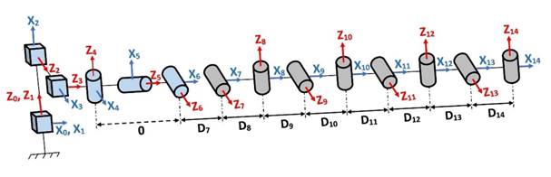
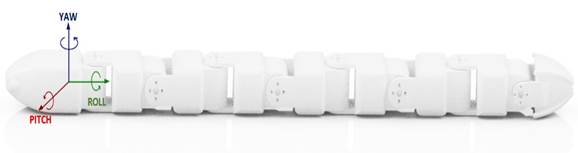
The geometric notation proposed by [24], [25] is used to calculate the kinematics of the entire robot structure. Then, the joint axes are identified and drawn on the snake-like robot structure, where the zj-axis is the axis of the j-joint and the xj-axis is perpendicular common to the zj and zj+1. axes. Figure 1 shows the location of each of these axes. To define the geometric parameters for each of the robot joints, which are identified in Table 1, the following considerations must be taken into account:
σj: type of joint (σj = 0 if the joint is a rotoid joint; σj = 1 if the joint is a prismatic joint).
αj: angle between the axes zj-1 and zj corresponding to a rotation around xj-1.
dj: distance between zj-1 and zj along xj-1.
θj: angle between the axes xj-1 and xj corresponding to a rotation around zj.
rj: distance between xj-1 and xj along zj.
Before the implementation of the robot prototype, it is appropriate to analyze if the mathematical model of motion based on sinusoidal waves can be applied to the robot. Thus, the model will be debugged in a simulation environment since reduces the risk of damaging any physical component of the robot. For performing the simulation, the identified geometric parameters used, which give us the representation of the position and orientation of the robot in its movement process.
2.1.2 Gate Types
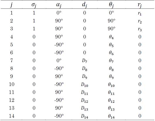
Snake robots must have the ability to switch between different gait modes to adapt and overcome difficult environments. In this work, to achieve to mimic the motion of a snake, locomotion modes based on Hirose's serpentinoid curve and its three-dimensional variations were implemented [19]. These curves can be described as sine waves propagating through the body, one for horizontal motion and another for possible vertical motion, as demonstrated in (1).

Where n is the motor number, Ax and Ay are the wave amplitudes, δ x and δ y is the spatial frequency, ωx and ωy represents the temporal frequency, and ϕ is the phase difference between the sine waves in the horizontal and vertical plane.
This paper will not consider unnatural gait modes and instead addresses lateral and rectilinear wavelet motions, which are two basic locomotion modes that allow the robot to adapt to different environments. Table 2 shows the variables for the two implemented gait modes.
Before the construction of the robot, it is convenient to analyze virtually the mathematical equations of motion with the selected parameters. Therefore, a simulation of the robot is performed using Matlab - Simulink software with the combination of the SimScape tool, which allows an efficient and fast multibody simulation, formulating and solving the equations of motion of any mechanical system.
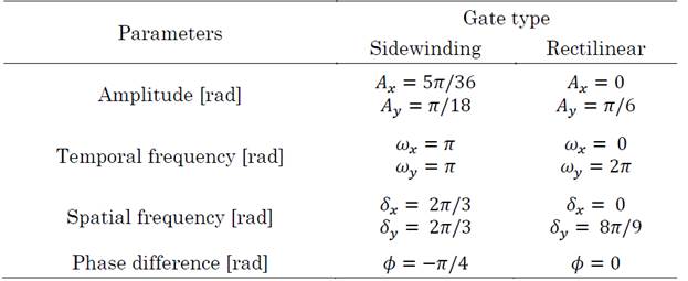
The simulations present the torque required to create the movement patterns and allow to check if the parameters chosen for the equations of motion produce the desired result. Consequently, the model can be debugged in the simulation environment without running the risk of causing unexpected motions and overloading the motors. Figure 2 shows the block diagram representing the robot, the floor, and the locomotion equations.
The above diagram is decomposed into several blocks. To determine the global reference frame of the model, the block (World frame) is used, and a 6-degree-of-freedom (6-DOF-1) joint is implemented, which represents the virtual orientation and positioning structure discussed in section 2.1. This joint establishes the initial position of the robot concerning the global reference of the system. Within the Robot block in Figure 2, the eight bodies, the tail, and the head of the robot are represented, which are connected to each other (see Figure 3).
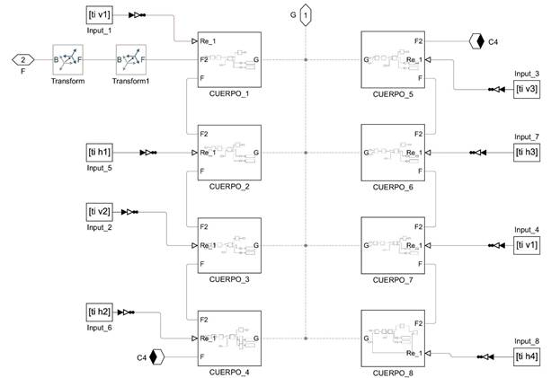
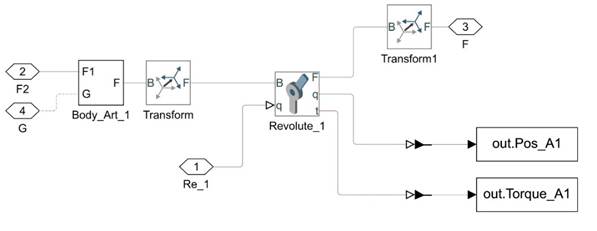
Additionally, some blocks called (Transform) can be observed, where the rotations and translations of the axes of each link are specified, which correspond to the kinematic solution presented in Figure 1. The body blocks inside each contain a rotational joint and a linkage position and torque signal output (Figure 4). In addition, the body block_1 contains the robot head.
The simulation confirmed that the desired locomotion modes could be created with (1).
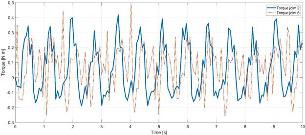
A maximum torque value was also obtained throughout the measurements on all joints. This maximum torque value was requirement for choosing the appropriate motors for the actual robot. Figure 5 presents the torques of two joints during the execution of the sidewinding gait. The maximum torque is approximately 0.48 Nm for the sixth joint, which was the highest torque obtained when verifying the results of the other joints in simulations for the sidewinding and rectilinear gait modes.
2.2 Robot Design
A modular design was preferred during the snake-like robot implementation, since the use of a modular architecture facilitates the replacement or addition of modules, in consequence, decreasing or increasing the degrees of freedom. The current design consists of 8 similar modules for each of the body links, in addition to a customized head module and a tail module.
2.2.1 Actuator
Many different types of drives can be used for snake robots, such as pneumatics, electric motors, servos, or driving wheels [26]. For this specific project, servo motors were considered. Considering the maximum required torque results of the simulations seen in Figure 5, the Dynamixel AX-12 servo motor was chosen. This servo motor has a built-in microprocessor to provide TTL or RS-485 serial communication and a daisy-chain speed of 1 Mbps ( 3 Mbps. It also features adjustable torque speed and responsive control with position, load, voltage, speed, and temperature feedback, allowing the implementation of a control system with relative ease. This servomotor reference runs at 12 V, weighs 55 g, and provides a torque of 1.47 Nm, providing a good margin above the 0.48 Nm required in the simulation.
2.2.2 CAD Designing
The snake robot modules were designed in SolidWorks software and then 3D printed. Each module is intended to function as a rotational joint with one degree of freedom as seen in Figure 6. The module consists of a housing, a Dynamixel servomotor, and an internal channel for a convenient disposition of the communication and power cables forming a serial bus.
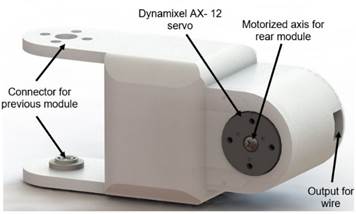
Each module of the robot is connected to the previous one positioning their axis of rotation as perpendicular and allowing a ± 90° rotation in comparison to its predecessor, as seen in Figure 7. This configuration allows two axes of motion in each pair of modules, which means that the robot can use three-dimensional gait modes. The current design consists of a head module, a tail module, and 8 symmetrical modules, which can be modified according to the application. Dimensionally the robot is 76cm long, with an approximate diameter of 5 cm, and a total weight of 2 kg.
3. RESULTS AND DISCUSSION
3.1 Experiment and Simulation Parameters
In this section, two of the four gait modes are validated using (1), and simulations as well as testing the real robot on a flat surface.
3.1.1 Test Setup for the Real Robot
The snake robot has a BNO055 IMU in the head, where the axis of rotation Yaw (see Figure 7), helps to verify the angle of deviation (or orientation) of the first link of the robot during the two proposed modes of operation. In addition, the robot is powered by an external 12 V supply, the chosen actuators use half-duplex asynchronous serial asynchronous TTL communication, facilitating a daisy chain connection. The motors are controlled through a laptop computer and a USB communication board (U2D2) to transmit the locomotion commands. The configuration for the experiment is seen in Figure 8. The distance from the start point to the endpoint was 1 m for the sidewinding locomotion mode tests, and 1.5 m for the rectilinear locomotion tests. For each of the locomotion modes, 10 experiments were performed and the time that that the robot took for reaching the end point was also collected.
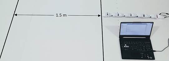
Finally, since the prototype of the snake robot does not have a sensor or a motion capture system attached, the centerline deviation data in the rectilinear gait were measured manually with the help of the vernier tool.
3.1.2 Webots Simulator
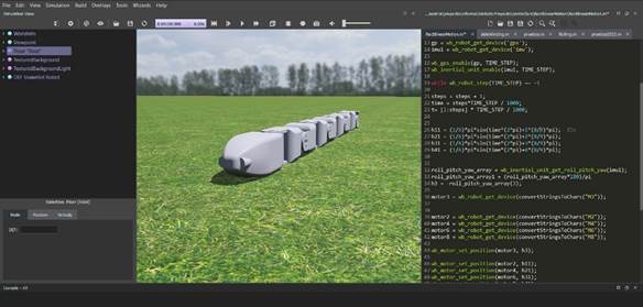
The Webots robotics simulator simulated the movements of the snake robot. This software, developed by Cyberbotics Ltd., provides multiple rapid prototyping tools for modeling, programming, and simulating mobile robots. For each object added to the program, physical parameters such as inertia matrix, density, texture, mass, and friction can be defined. In addition, it allows equipping the robot with a large number of available sensors and actuators.
The shape of the robot was imported directly from CAD models designed in SolidWorks software to Webots as shown in Figure 9. The physical properties of the robot, the maximum speed, and the torque of the motors were included in the simulated robot. Also, the current model has sensors such as IMU and GPS to obtain the exact global position of the robot. Webots allowed to quickly evaluate the performance of the robot, and in particular its behavior on completely flat terrain.
3.2 Simulation and Experimental Results
3.2.1 Sidewinding Gate
This section presents the results obtained by running the sidewinding gait pattern experiment. This mode was included because it is commonly used in projects related to snake robots. Therefore, we want to demonstrate that using (1) and the parameters described in Table 1, the desired forward motion is obtained. To achieve this, a value different from 0 is placed on the phase difference ϕ, for example for a value of -π/4, the robot moves forward to the left concerning the direction in which the head is pointed. Figure 10 shows two views of the position of the real and simulated robot executing the sidewinding type gait.
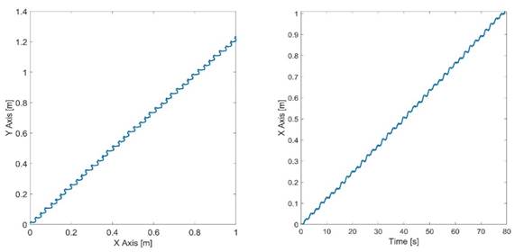
For the Webots simulation of the sidewinding locomotion type, the robot had to reach a distance of one meter on the X-axis. The experiment was repeated 10 times, in which the distance on the Y-axis and the time taken to complete each trial were approximately the same (see Figure 11).
Source: Created by the authors.
Figure 11 Path of snakehead position and distance vs. time for the simulated sidewinding gait pattern
It is observed that the path taken by the robot is as expected, performing a displacement to the left of the robot's head as it advances until reaching the meter on the X-axis. The time taken for each of the simulations was 79.168 s and the distance reached on the Y-axis was 1.234 m. Subsequently, the 10 experiments were carried out with the real robot. where the following results were obtained: the time of the tests was 80.089 s ± 1.96 s and the displacement in the Y-axis was 1.295 m ± 0.052 m. The latter, suggests that these values are very close to the simulated ones, since, on average, the difference in the simulation time is less than one second and the distance was greater in the real robot with a difference of approximately 6 cm. One of the possible causes of said difference in the displacement is that the robot must pull the external source, thus counteracting the weight of the power cable. In addition, during the tests performed, it was observed that the actual robot had a slight inclination to the left in each execution cycle, which is an additional factor that could affect its movement and contributed to the results obtained in simulation.
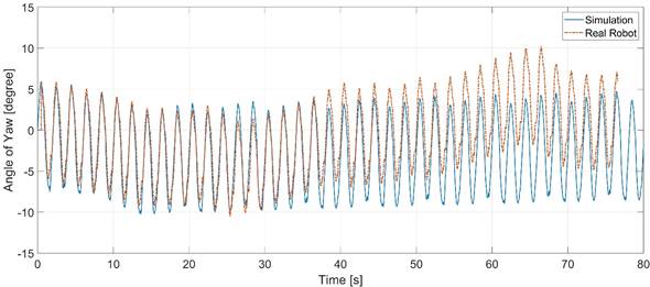
Figure 12 presents a graph comparing the simulated values with the experimental values of the Yaw angle recorded by the IMU located in the robot’s head. Notice that sidewinding motion is a three-dimensional gait mode in which two sinusoidal waveforms interact to generate alternating forward/backward and left/right movements. The figure shows the horizontal movements of the head, where angles ranging in the simulation range from 5° to -10° are obtained. Even, up to 50 seconds there is a great similarity in the comparison of results, then, the angle readings on the actual robot may be affected due to the noise generated by the stress when the external power supply starts to crawl, changing the initial state of the reading of the three IMU rotation axes.
3.2.2 Rectilinear Gate
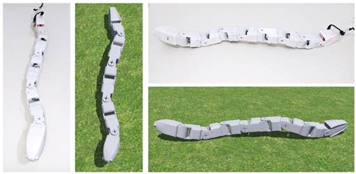
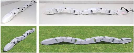
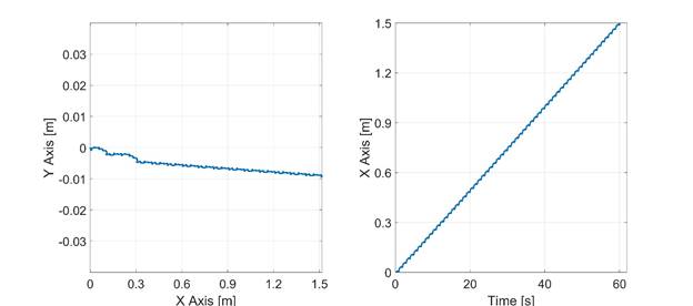
Rectilinear motion is common among boas since they have large bodies. Figure 13 presents images of rectilinear locomotion tests both in simulation and the real robot. Although this type of locomotion is slow and inefficient in motion, it would allow a snake robot to pass through narrow circular or linear pipes, where it is difficult to perform other forms of gait. Figure 14 presents the position tracking results of the robot’s head in one of the ten tests performed with the simulation software.
Source: Created by the authors.
Figure 14 Snakehead position path and distance vs. time for the simulated rectilinear gait pattern
From the previous figure, it can be observed that the robot does not have a full rectilinear behavior, presenting a slight deviation to the right of 8.9 mm on the Y-axis, which is insignificant in the short runs. The simulation time in each of the tests that the robot took to reach 1.5 m was 60.064 s, obtaining a speed of 2.49 cm/s.
With the real robot, a small deviation of less than 3 cm is also observed in each of the tests. The average of this deviation with respect to the Y-axis is 1.97 cm ± 0.87 cm, with a total run time of 60.69 s ± 0.85 s, for a mean speed of 2.47 cm/s. the results presented above see suggest that the data of this locomotion mode are closer between the physical robot and simulation than those obtained in the sidewinding gait. Figure 15 shows the Yaw angle or angle of rotation with respect to the vertical axis perpendicular to the robot.
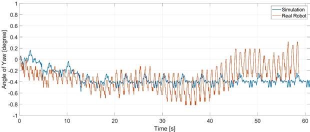
It can be observed that during the first 15 seconds of the execution of the rectilinear motion in the robot a deviation angle is generated that increases progressively until it oscillates up to -0.4°. This angle of rotation does not significantly affect the trajectory of the robot as shown in the left graph of Figure 13. unlike what can be observed in the real robot, where the angle presents greater oscillation, but always with values close to zero. This deviation may be a consequence of the design and construction of each of the rounded edges of the robot bodies, as well as the effort made by the robot when dragging the external power supply. In addition, during this gait mode, the motors of the odd joints should not move and their setpoint should remain on zero, which is currently not being accurately controlled in the locomotion algorithm.
Although there are several sources of error influencing the data acquired by the real robot, we see that the plots comparing simulation and experimental results provide a satisfactory description of the system before validating the proposed robot. Furthermore, the simulation software and the physical parameters included in it form a fairly accurate model of the snake robot.
4. CONCLUSIONS
This article presented the design of a snake-like robot, its modeling in CAD software, and its subsequent simulation. The robot was built using eight Dynamixel AX-12 servomotors, which facilitate daisy-chaining and serial TTL communication. The robot also has an inertial measurement sensor (IMU) to obtain rotation angle data. In total it has six motors for the body and two more that serve as the head and tail of the body.
The simulation of the robot was first performed in the Matlab - Simulink environment, using the SimScape tool, where the initial model was tested with its respective mathematical equations, and the necessary torques for the motors were obtained. Then the Webots mobile robotics simulation software was used, which allows the synthesis and testing of various movement patterns in two and three dimensions for the snake robot. Two walking modes were tested both in simulation and with the real robot: sidewinding and rectilinear. The results obtained show two interesting behaviors: first, the tests in simulation and with the real robot are quite similar; second, the behavior of the real robot is satisfactory in short runs, with a small deviation error mainly attributable to the fact that the robot has to drag the source that feeds it energetically. Future work will implement other modes of locomotion, in addition to testing its behavior in uneven terrain to apply correctives in both its architecture and its control, so that it can perform tasks with greater versatility. This could be achieved by adding sensors that can acquire data from the terrain to overcome irregular surfaces.

