


 English (pdf)
 Article in xml format
 Article references
 Send this article by e-mail
 Cited by SciELO
  Cited by Google
  Similars in
SciELO
Similars in
SciELO  Similars in Google
 Permalink
INTRODUCTION
Autonomous navigation is essential in service robotic applications such as automated agriculture, self-driving cars, driver assistance, monitoring and security, and search and rescue. In these fields, computing precise local maps of the surroundings is an important task, where the autonomous vehicle can locate itself and achieve the intended goal. Common sensors for this are LIDAR, GPS, cameras, and a combination of these sensors. LIDAR sensors are highly precise, but they are expensive; GPS sensors do not work in all outdoors environments and their sample time is low; cameras are cheaper, capture near 3D information, can be part of any mobile platform and offer visual information which is also useful to enrich Human-Robot interfaces.
An important task in autonomous navigation is road-following and tracking. In this context, scientific literature divides road-following and tracking methods in two groups top-down and bottom-up. The former uses whole the image information to estimate the road heading; the latter uses features such as color, texture, edges between others to estimate the road heading. This work uses the bottom-up approach, particularly the detection and estimation of vanishing points (VP), since this feature improves the robustness and effectiveness of road heading in many types of roads [1].
This paper presents the software tool AutoNa-vi3AT [2], which is a software tool capable of configuring and controlling a Pioneer 3AT mobile robot to follow an urban road using omnidirectional vision. The omnidirectional vision was selected since it presents better field of view and has a high feature lifetime. AutoNavi3At detects VPS in the panoramic images using Gabor filters and region growing. However, these estimations are unstable since they depend on the illumination conditions; for this reason, a particle filter was implemented to track the VPS to then use this VP as heading reference of the mobile robot motion when navigating the road. The contributions of this work are as follows:
■ Reliable and accurate VP estimation to guide the mobile robot on an urban road.
■ Implementation of a real time guidance system on a mobile robot base on VP estimation and particle filters.
■ From operational point of view, AutoNavi3AT is a friendly mobile application to configure and control the VP estimation, and robot navigation.
The rest of this work is structured as follows: related works, the urban road-following methodology, the design and implementation of AutoNa-vi3AT, tests and results, and conclusions.
RELATED WORKS
Table 1 shows the works most relevant to this paper. It compares the reviewed work considering their application, sensors used, the method proposed for road segmentation, and features used to estimate the road direction.
Table 1 Related work.
| Ref. | Application | Sensors | Method | Features |
|---|---|---|---|---|
| [3] | DARPA challenge | Monocular | OLDOM | VP |
| [4] | Non-urban navigation | Monocular | Gabor filters | Road texture |
| [5] | Non-urban navigation | Monocular | Gabor filters | Road texture |
| [6] | Non-urban navigation | Monocular | MPGA | VP |
| [1] | Non-urban navigation | Monocular | Gabor filter | Road texture |
| [7] | Non-urban navigation | Monocular | Optical flow | FOE, vp |
| [8] | Urban, non-urban nav. | Monocular | Morf. Oper. | Texture, edges |
| [9] | Urban navigation | Monocular | ICNet, VP | Texture |
| [10] | Urban navigation | Omnidirectional | 3-line Ransac | Lines, vp |
| [11] | SLAM | Omnidirectional | EKF | KLT |
| [12] | Urban navigation | Omnidirectional | DBSCAN | vp, edges |
| [13] | Non-urban navigation | Stereo | M. Gaussian | vp, edges |
| [14] | Urban navigation | Lidar | Otsu | Line marks |
| [15] | Urban navigation | Camera, laser | Adaboost, vp | Texture, edges |
Source: Own elaboration
As seen in Table 1, these works can be classified in three groups considering the sensor used: monocular camera [1], [3]-[9]; omnidirectional camera [10]-[12], and other sensors such as stereo cameras [13], LIDAR [14] and a combination of monocular and Lidar sensors [15]. Monocular cameras are cheaper and easier to mount in autonomous vehicles, but their field of view is limited. LIDAR sensors are highly precise, their field of view is wide, but they are very expensive in comparison with the vehicle's cost. Stereo cameras are now more common, and their biggest advantage is depth perception; however, as with the omnidirectional camera, they are least studied despite the fact they offer a larger field of view, which increase the feature lifecycle for tracking purposes.
Most road-following applications include urban and non-urban vehicle navigation. In urban navigation, works such as [8]-[10], [12], [14] and [15] exploit the fact that autonomous vehicles are driven in marked lanes with visible lane border to segment the road using morphological operators [8], deep learning approaches [9], robust RANSAC estimators [10], clustering edges using DBSCAN [12], thresholding [14], and Adaboost classifiers [15]. Non-urban navigation is more challenging, since it assumes there are no lane markers, and it is difficult to distinguish the road from surrounding vegetation. In this context, works such as [1], [3]-[5] use Gabor filters to segment the road using texture, [6] uses a genetic algorithm (MPGA) to classify road super-pixels, [7] uses the relative position of the focus of expansion and the road VP to get the road direction using optical flow, and [13] uses multivariate Gaussian approaches to extract VPS.
Finally, Table 1 shows that the main goal of most methods is obtaining the scene VPS. It does not matter if the autonomous vehicle is driving in urban or non-urban roads since VPS detection is robust in all types of roads [1]. For this reason, in this work accurate estimation of VPS is an important task which is detailed in the next section.
URBAN ROAD-FOLLOWING USING OMNIDIRECTIONAL VISION
The urban road-following task implemented in this work is inspired by [13], but it was adapted to process omnidirectional images, which has impact in different stages of the algorithm such as Gabor filtering, region growing and the voting schema to predict the VP. Basically, the pipeline of the main algorithm implemented in the mobile robot is described as follows:
1) The omnidirectional image is captured and then converted to a panoramic image using the calibration parameters.
2) The predicted VP is computed using Gabor filters, dominant orientation calculation, and filtered region growing.
3) The most likely VP is estimated using a particle filter.
4) Finally, the robot final heading is calculated based on three components: the estimated road direction, the heading computed by the obstacle avoidance task and the user entry.
The captured omnidirectional image is converted to a panoramic image using (1) [16].
Where, u and v are the panoramic image coordinates, r j and θ j are the radial distance and angle of the i-th pixel in the omnidirectional image, and cx and cy are the center coordinates of the omnidirectional image. Using this panoramic image, a set of Gabor filters are applied using (2).
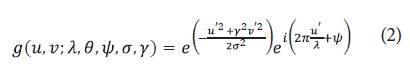
Where, λ is the wavelength of the sinusoidal factor, θ is the filter orientation, Ψ is the filter phase offset, a is the standard deviation of the filter Gaussian, and y is the spatial aspect. In this work, filter parameters such as λ, σ and kernel size were tuned using [17]. The number of Gabor filters for this work was 8, each at 22.5° uniformly distributed between 0° and 180°. This set of filters is applied to the panoramic image, but their energy response in terms of magnitude and orientation are computed. These responses are then sorted in descendent order and (3) is used to compute their confidence level [17], and then to obtain the dominant orientations.
Where, p is a pixel in the panoramic image, theta is the number of Gabor filter orientations, and E i is the sorted energy response of each filter. All pixels less than a confidence threshold are discarded. In our experiments, this threshold was set to 30. The next step is region growing; to do that, a robust number of pixels in the region (n reg ) is computed using (4) [17].
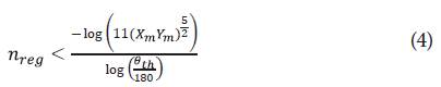
Where, X m and Y m are the image dimensions, and θth is the Gabor filter orientation resolution. Next, all pixels corresponding to a dominant orientation are used to fit a region around them, and a line segment is inscribed within a rectangle. Experiments show that the height of this rectangle should be twice width. Additional constraints are needed to obtain better line segments candidates and avoid situations such as line segments pointing to outer image regions (left, right, up and below the image). In (5) the second constraint is applied to the line segments.
Where, Ci,x is the line segment mean x coordinate, C xmean is the average of all x coordinates line segment, and K are the line segment slopes. The resulting line segments are used to predict the vp in a weighted voting schema defined by (6).
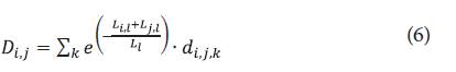
Where, L i,l and L j,l are the length of a pair of line segments L i and L j ; L l is the total length of all line segments, and d i,j , k is the distance from a line segment L k to the intersection point of line segments L i and L j . Then, the VP selected p vp (x i,j , y i,j ) corresponds to the minimum weighted vote D i,j .
Despite the above filtering process, the VP detected is noisy due changes in the illumination and obstacles in the road. A more robust estimation is needed since this VP will be used to define the mobile robot heading direction. For this reason, in this work a particle filter was implemented to better estimate the VP. Three major components are needed to do so: a particle set, the transition model and the measurement model. The particle set is composed by a sample of VPS {s m t , m = 1, ..., M}, and M corresponding weights {w m t , m = 1, ... , M} [18], where sj t = (x j t , y j t ) is a VP hypothesis in image coordinates.
The M VP samples of the particle set are obtained using a two-dimensional Gaussian distribution with μ. = (0, 0) centered in the predicted VP, and Σ with two diagonal elements equal to (σ xmean , σ ymean ) corresponding to the standard deviation values of the line segment center coordinates, see (5). Then, the transition model depicted in (7) is applied to the particle set to obtain the next state probability distribution.
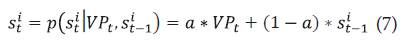
Where, s t i is the i-th vp hypothesis sample at time t, p(s t i | VP t , s i t-1 ) is the Gaussian probability distribution function applied to the predicted vp (VP), which depends on the previous state (s i t-1 ) and the constant a is defined in (8).
Where, a is the norm of a unit vector computed between the difference of the i-th predicted vp at time t (VP), and the i-th vp hypothesis sample at time t-1 (s i t-1 ).
In particle filters, the measurement model is used to compute the particle weights. The relationship between the particle weights and the measurement model is shown in (9).
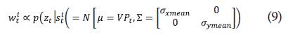
Where, w i t is the i-th weight corresponding to the i-th vp hypothesis, and p(z t | s t i ) is the probabilistic measurement model which uses a normal distribution with mean equal to the predicted vp (VP) and covariance matrix Z. Then, after the resampling process, the estimated vp selected is the hypothesis with the greater weight.
Finally, the fourth stage needs three heading components. At this moment, the estimated road direction is now available (s q t ). Another component comes from the obstacle avoidance node, which uses potential fields [19] to compute a heading free of obstacles (PF q t ). The third component comes from user inputs (U q t ), which are summarized as follows: go forward, turn left, turn right, and perform a U-turn. These user inputs are used only in the moment that the mobile robot faces a cross street intersection. Otherwise, the mobile robot motion responds to the final heading computed in this fourth stage. Then, the final robot heading is computed as depicted in (10).
Where, k, l and m are constants to merge the three headings expressed in quaternions. In this work, k = 0.2, l = 0.3 and m = 0.8 After computing (10) the final heading quaternion h q t is normalized and sent to the mobile robot. The normalization procedure is needed in case the obstacle avoidance or user input headings are not available.
DEVELOPMENT OF AUTONAVI3AT
This section describes the design and implementation of AutoNavi3AT. AutoNavi3AT was developed using the RUP methodology [20]; this methodology includes the following deliverables: functional and non-functional requirements, conceptual diagram, use cases, sequence diagrams, class diagrams, source code, and tests reports. Due to space reasons, this section describes functional and non-functional requirements, ROS node diagram and GUI description.
DESIGN OF AUTONAVI3AT
Considering the related works analysis performed above the functional and non-functional requirements of AutoNavi3AT are described as follows:
■ Functional requirements: A friendly GUI in a portable device to configure parameters of the Gabor filters, laser sensor, and obstacle avoidance, as well as operate the mobile robot; capture omnidirectional images and obtain the corresponding panoramic image; compute the estimated road heading using Gabor and particle filters; avoid obstacles in the road using a laser sensor; gather user inputs when the robot faces cross street intersections; and, navigate the mobile robot in urban roads.
■ Non-functional requirements: The development environment is ROS Indigo; the mobile robot platform is a Pioneer3AT; the portable device Android SO minimum version is 6.0; the vision sensor includes a Prosilica camera GT1290C and an omnidirectional optics GoPano Plus.
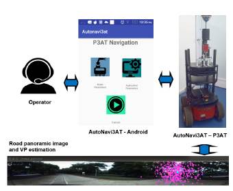
Fig. 1 shows the conceptual diagram of Au-toNavi3AT. Here, the operator or user accesses the AutoNavi3AT functionalities through the Android-based GUI. Using this GUI, users can modify the robot and algorithm parameters, then execute the autonomous navigation algorithm on urban roads. This algorithm computes the vps of the panoramic scene; since vps are sensitive to illumination changes, the particle filter tracks and estimates the most likely vp. Users also can command the mobile robot when it faces a cross street intersection. The experimental platform is a Pioneer 3AT mobile robot, which is equipped with an on-board Linux Ubuntu 16.04 computer, a laser range finder Hokuyo UTM-30LX, and a Prosilica GT1290C camera with a parabolic omnidirectional catadioptric optic.
IMPLEMENTATION OF AUTONAVI3AT
As depicted in Fig. 1, AutoNavi3AT was implemented in two main parts: first, the GUI in the Android device, and second the ROS application in the mobile robot Pioneer 3AT. The GUI in the Android device responds to a navigation diagram shown in Fig. 2. The P3AT Navigation activity includes access to the Robot Settings, Application Parameters and Execution activities. Users can modify robot settings such as robot speed, laser range finder interest region, and the omnidirectional calibration parameters. The latter were calibrated using [20].
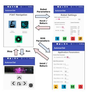
Also, users can modify application parameters, such as the number of particles and the Gabor filter parameters. Once robot and application parameters are set, users send these parameters to the mobile robot and return to the main activity. In both cases, default parameters always are available in case of user error. Then, returning to the main activity, users can execute the ROS application in the mobile robot and send commands to it such as turn left, turn right, go forward, and perform U-turns. In the execution activity, the mobile robot sends the current omnidirectional image processed which shows the predicted and estimated vps.
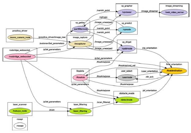
The second part of AutoNavi3AT is an ROS application which runs in the on-board computer of the Pioneer 3AT. This kind of application is represented as a map of nodes. Fig. 3 shows this representation for the AutoNavi3AT software tool. Here, the following nodes can be identified:
■ The beige nodes /mono_camera_node and / imcapturer correspond to the omnidirectional image acquisition.
■ The cyan node /vpnode implements the vp prediction detailed above.
■ The purple nodes /partfiltermode, /vpviewer, / vpdimode and /web_video_server implement the estimation of the vp using particle filters and its visualization.
■ The green nodes /hokuyo_node, /laser_filtering and /detectnode implement the obstacle avoidance process using potential fields.
■ The grey node /usemode captures the user inputs in case the robot faces cross street intersections.
■ The yellow node /finaldestination implements the final heading calculation using (10).
■ The pink nodes /RosAria and /rosbridge_web-socket are ROS utilities used to command the Pioneer 3AT mobile robot and access its internal sensors and to communicate with the Android application. This communication is done by JSON objects, which include information such as the robot settings, ROS application parameters, user inputs, and visual feedback of the current omnidirectional image with the predicted and estimated vps on it.
RESULTS AND DISCUSSION
In this section, the experimental setup is described as well as the tests and results achieved after validating the functionalities of AutoNavi3AT. An example of the operation of AutoNavi3AT can be found in https://www.youtube.com/watch?v=DXl-gjERggMU, which shows how the software tool is used on the internal roads of the Universidad del Valle, close to the School of Electrical and Electronic Engineering (EIEE, for its initials in Spanish).
EXPERIMENTAL SETUP
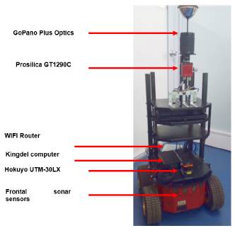
Fig. 4 shows the Pioneer 3AT robot base with the following sensor setup: a Prosilica GT1290C camera, a GoPano Plus omnidirectional optics, and a Hokuyo UTM-30LX laser range finder. The Pioneer 3AT robot also has a WiFi router as the remote communication interface, two incremental encoders of 500 ticks/rev, eight frontal sonar sensors, one on-board Kingdel computer running Ubuntu 14.04 and Ros Indigo, and three battery pack of 12V / 7Ah.
TESTS AND RESULTS
To validate the functionalities of AutoNavi3AT, two different experiments were performed: a dataset-based test and a field test. The goal of the dataset-based test is to check that all functional requirements described above can be satisfied and that those with issues can be improved. Once these issues are corrected, the goal of field tests is to validate the functionality of AutoNavi3AT in real world conditions. In both tests, accuracy of the vp estimation is measured quantitatively over several runs.
DATASET-BASED TESTS
To perform the dataset-based tests, a dataset was acquired for the internal roads of the Universidad del Valle, close to the ¿EIEE. This dataset includes five routes as depicted in Fig. 5 and includes the following data: omnidirectional images, laser scan data and odometry information. The datasets are stored as rosbag compatible files. The datasets were acquired in real environmental conditions, with changing illumination and obstacles and rubbish in the road.
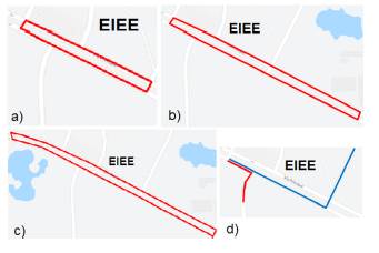
Fig. 5 Datasets. a) Route No. 1 (426m). b) Route No. 2 (800m). c) Route No. 3 (1.02Km). d) Route No. 4/5 (317m / 120m)
In all routes shown in Fig. 5, the amount of data logged in the rosbag files ranges from 850 data points to 2500 data points. Since these experiments were performed at different dates and time, they are independent of each other; a Gaussian distribution for error analysis can be assumed. The goal of the error analysis in this work is to show an improvement with respect to [13], since, in this work a particle filter is used to improve the vp estimation.
Using these datasets, the proposed method described above was tested. The results obtained include the XY coordinates of the predicted and estimated vp over the whole route. Fig. 5 shows the graphs for all five routes, at each figure the predicted and estimated XY coordinates are shown, as well as a sample panoramic image. The predicted vp is shown in magenta, and the estimated vp is shown in blue. Same color code applies to the vps shown in the panoramic image.
Observing Fig. 6, predicted vps have large variations over the route, which mainly is due to changing illumination and rubbish on the road which affect the road segmentation. These experimental data justify filtering the vp location data. In this work, a particle filter was implemented to better estimate the vp location as described in above. Observing the blue traces in Fig. 6, a noticeable improvement is obtained using the particle filter proposed in this work.
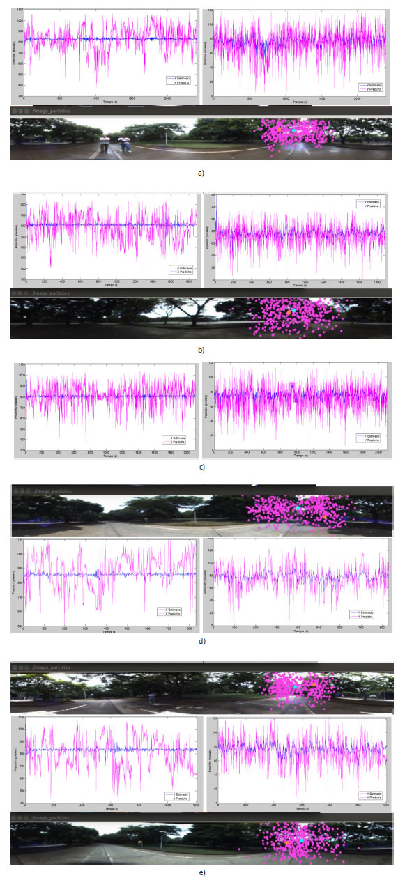
Fig. 6 Predicted (magenta) and estimated (blue) X-Y vanishing point coordinates, as well as sample of panoramic image. a) Route No. 1. b) Route No. 2. c) Route No. 3. d) Route No. 4. e) Route No. 5
Table 2 shows the quantitative results for all five routes, where the mean of XY vp coordinates (predicted and estimated) including 1a standard deviation over the whole route is shown. The data variation of Table 2 shows high improvements ranging from 2.5 to 8 times for the X coordinate, and from 1.6 to 7 times for the Y coordinate. The last rows of Table 2 show the mean improvement percentage considering the uncertainty measures and computed for each route using (11).
Where σ Est is the standard deviation of the estimated vp, and a Pred is the standard deviation of the predicted vp. Observing these results, the estimation of the vp X coordinate can be improved by up to 77.3% in average; and up to 59.2% for the vp Y coordinate.
Table 2 Quantitative resuits of dataset-based tests.
| State | Coord. | R. 1 | R. 2 | R. 3 | R. 4 | R. 5 |
|---|---|---|---|---|---|---|
| Predicted | X | 824.5 ± 73.04 | 790.69 ± 109.34 | 816.09 ± 99.85 | 883.83 ± 112.95 | 793.81 ± 104.19 |
| Y | 59.35± 18.32 | 70.58 ± 16.55 | 70.55 ± 16.01 | 77.19 ± 17.94 | 68.66 ± 17.32 | |
| Estimated | X | 807.83 ± 14.91 | 807.78 ± 42.87 | 808.09 ± 25.06 | 858.28 ± 14.11 | 807.64 ± 17.0 |
| Y | 72.72 ± 10.98 | 77.64 ± 6.19 | 77.52 ± 5.8 | 78.79 ± 5.89 | 76.64 ± 6.48 | |
| Improvement in X | 79.59% | 60.79% | 74.9% | 87.51% | 83.68% | |
| Improvement in Y | 40.06% | 62.6% | 63.77% | 67.17% | 62.59% | |
FIELD TESTS
Three additional field tests were performed using the Pioneer 3AT mobile robot. First, a straight-line route of 30 m; second, a turn right route of 15 m; and third, an obstacle avoidance test of 20 m. Fig. 7 shows the results of these tests, where the XY predicted (magenta) and estimated (blue) vp coordinates are shown, a snapshot of the mobile robot moving over the route, and the robot orientation perceived by the robot sensors. These results show a behavior similar to those depicted in Fig. 6, where the particle filter proposed in this work helps to improve the uncertainty in the vp estimation. In addition, the robot orientation graph for all three routes shows the results expected, namely a soft robot heading of 0 rads, a turn to the right at approximately 70 s of the test, and an obstacle avoidance at t = 30s and recovering the road orientation at 45 s. Even though the road had rubbish on it, shadows and changing illumination, the robot heading behaves smoothly, a desired behavior for autonomous vehicles.
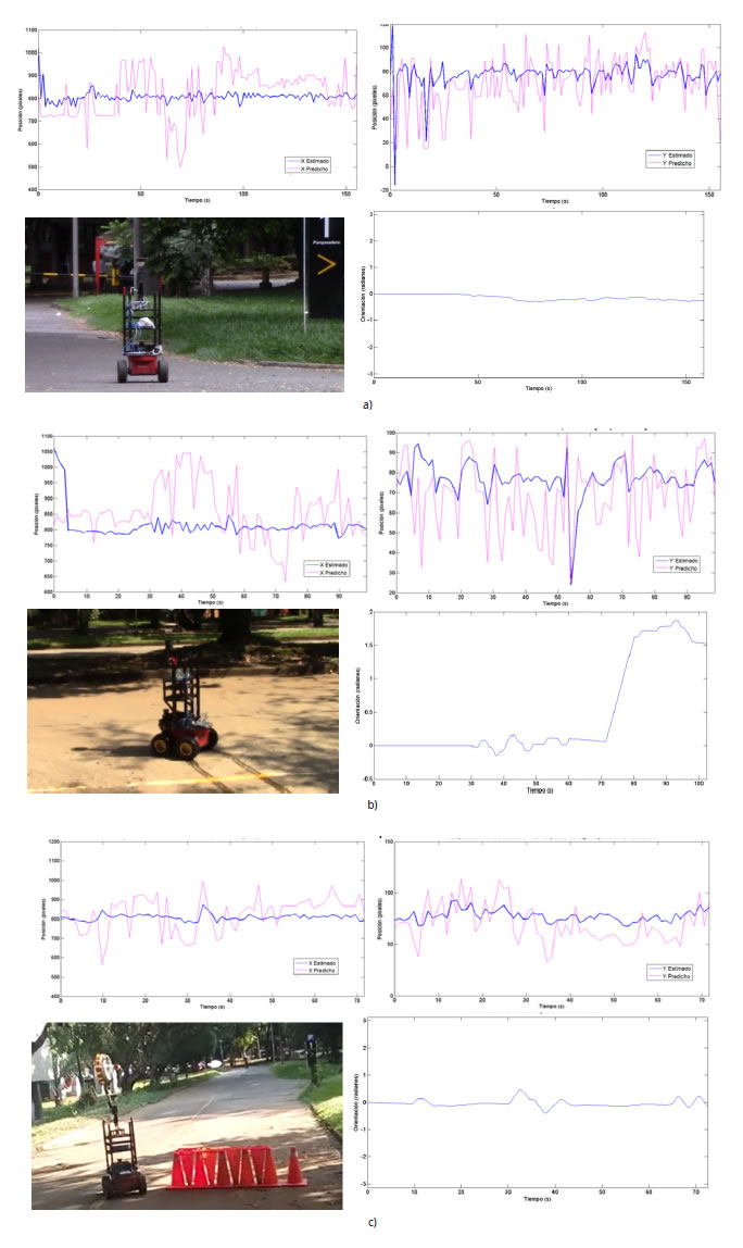
Fig. 7 Predicted (magenta) and estimated (blue) X-Y vanishing point coordinates, an image sample of the test and the robot orientation. a) Test No. 1. b) Test No. 2. c) Test No. 3.
As in Table 2, Table 3 summarizes the quantitative results obtained, showing improvements in the uncertainty ranges from 1.8 to 5.5 times in the X coordinate, and from 1.9 to 3.3 times for the Y coordinate. Applying (11) to the experimental data shown in Table 3, on average the vp X coordinate improved by 67%, and the vp Y coordinate by 55%.
Table 3 Quantitative results of field tests.
| State | Coord. | Test 1 | Test 2 | Test 3 |
|---|---|---|---|---|
| Predicted | X | 821.04 ± 106.1 | 857.65 ± 87.84 | 827.54 ± 90.15 |
| Y | 70.14 ± 22.21 | 68.78 ± 18.02 | 70.19 ± 18.82 | |
| Estimated | X | 808.36 ± 26.15 | 814.66 ± 47.58 | 808.47 ± 16.13 |
| Y | 77.14 ± 11.69 | 76.95 ± 9.28 | 77.7 ± 5.72 | |
| Improvement in X | 75.35% | 45.83% | 82.11% | |
| Improvement in Y | 47.37% | 48.5% | 69.61% |
CONCLUSIONS
This work describes the AutoNavi3AT software interface, which is a solution composed of two main parts: a GUI on an Android device to configure and command a mobile robot for urban road navigation, and a Ros application which estimates the scene vanishing point using omnidirectional images, Gabor and particle filters. AutoNavi3AT was developed considering the RUP software development methodology, and the main functional requirements included processing laser scan data to avoid obstacles on the road, gathering user inputs when the robot faces cross street intersections and communicating the Ros application with the GUI using JSON files transferred through web-sockets.
Two kind of tests were performed, dataset-based and field tests. Dataset-based tests required the acquisition of a dataset with five different roads and stored as a rosbag file; the dataset have routes with lengths ranging from 120 to 1.02 Km. This dataset was acquired in real environment conditions including changing illumination, obstacles, and rubbish in the road. Using this dataset, the predicted XY and estimated vps coordinates were captured, and, considering Fig. 6 and Table 2, the estimation of the VP X coordinate was improved up to 77.3%, and up to 59.2% for the vp Y coordinate.
In addition, three field tests were performed: straight-line, turn to the right and obstacle avoidance. The route length in the field tests ranges from 15 m to 30 m. Then, considering Fig. 7 and Table 3, the VP X coordinate was improved up to 67% and the VP Y coordinate up to 55%. These results show that the proposed method in this work is a good option for autonomous navigation in mobile robots, filtering changing illumination of omnidirectional images, challenging road segmentation, merging heading references with local planning (obstacle avoidance) constraints and, if required, user inputs at specific moments in the robot navigation task.

