


 Inglês (pdf)
 Artigo em XML
 Referências do artigo
 Enviar este artigo por email
 Citado por SciELO
  Citado por Google
  Similares em
SciELO
Similares em
SciELO  Similares em Google
 Permalink
Introduction
This paper describes and analyses the complex failure of an under-dip shale slope discovered in Chongqing west Railway Station, which involves three mechanisms: sliding in the upper part, buckling in the lower part and toppling at the toe.
The bedding dip angle (68°) of the slope is larger than the slope angle (45°) and it is comprised of shale. Shale is a typical soft and fragile sedimentary rock, which is mainly comprised of clay mineral and always has obvious thin foliations called lamellation and the ease with which this rock splits along the direction of the lamellation weakens its resistance to erosion and weathering. Shale exhibits strong foliation, the long-term influence of gravity, groundwater, rainwater infiltration, and weathering can weaken the form, resulting in deeply weathered deformations and colluvium, which facilitates shale slopes to become prone to failure. The underlying failure mechanism was analyzed using a combination of geological analysis and numerical models in this paper.
Recent work on failure mechanisms has concentrated on buckling deformations on consequent slopes where penetrative discontinuities dip into the slopes (Cavers, 1981; Choquet &Tanon, 1986). However, Lugeon (1933) suggested that toppling deformation also occurred on slopes where penetrative discontinuities dip more steeply but in the same direction as the slope. Such slopes in which the discontinuities dip under the slopes are called under-dip slopes (Cruden, 1989).
Some failures on under-dip slopes were found in the Highwood Pass in Kananaskis Country, Alberta, Canada by Tang (1986) and in the Yellow head Pass by Cruden (1989). Cruden (1989) showed that, with the assumptions of Goodman and Bray (1976), toppling could occur on under-dip slopes without the assistance of external forces. Several researchers conducted studies on the failure mechanism of the under-dip stratified rock slope. Hu (1994) investigated the topples found by Tang (1986) and report modes and discontinuities characteristic of topples on under-dip slopes, analyze geological controls of toppling and explain the processes of toppling on under-dip slopes. However, the deformation modes of slopes vary with geological structures, strength of rock blocks and topography. These studies only concentrate on the overall toppling deformations of the under-dip slopes in some particular cases, which is not comprehensive approach, and it has been proved in some engineering examples that the failure mechanism and deformation characteristics of these under-dip slopes prove complicated, which involve a series of processes such as sliding, buckling and flexural toppling deformation.
Researchers adopted different methods to investigate the failure mechanisms of slopes. Numerical modeling techniques such as FEM, DEM, NMM have also been developed and applied for studying the complex failure of the rock slope (Alejano et al., 2010; Pritchard & Savigny, 1990; Pritchard & Savigny, 1991). Among the various numerical methods, the distinct element code UDEC has been widely used to investigate a wide variety of rock slope failure mechanisms including those ranging from simple planar mechanisms to complex deep-seated toppling instability and buckling (Stead & Eberhardt, 1997).
Although different failure modes of slopes are described in the literature, studies involving the deformation modes discovered in this paper are rarely seen.
Terrain and geology of the study area
Terrain of the area
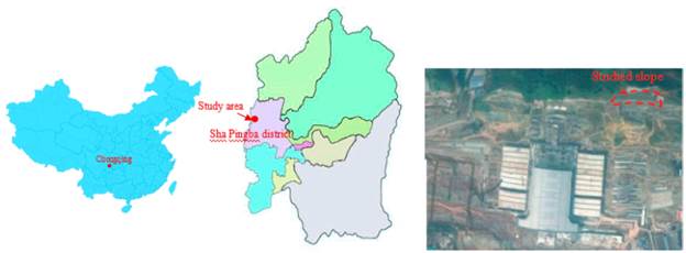
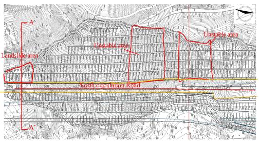
Chongqingxi Railway Station under construction is located in the Sha Pingba District of Chongqing. It is a traffic hub which is based on railway and gathers passenger transport, bus, and light railway, which will be the biggest traffic hub in Chongqing after the construction is completed. The study area for this paper is the No.6 slope, which ranges from K1+080 to K1+620 (Fig. 1). It is excavated on different steps with 10m high of each step, the landslide occurs at K1+500~ K1+520 (Fig. 2, Fig. 3), the slope studied in this paper is an under-dip shale slope, the bedding plane spacing is 0.1-0.3m. Figure 4 presents the engineering geological section of the slope at cross section A-A'. Shale is a typical soft and fragile sedimentary rock, which exhibits strong foliation, the long-term influence of gravity, groundwater, rainwater infiltration, and weathering can weaken the form, resulting in deeply weathered deformations and colluvium.
Geological features of the area
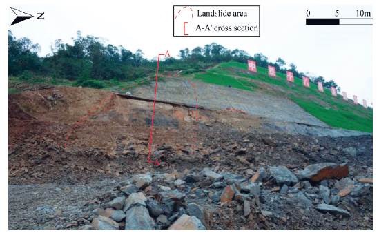
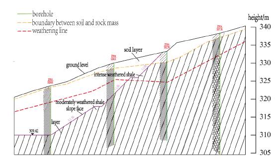
Figure 5 presents the failure characteristics of the slope at cross-section A-A' .The length of sliding mass along slope is over 30m, the height is over 8m, the rock mass is intense and intermediary weathered shale, the mechanical properties of the smooth and wet bedding plane is rather poor, It is present with an orientation of 90°/46°, the maximum depth of the sliding mass is 60cm, the sliding distance of rock mass in the upper sections of the slope along the bedding plane is about 1m (Fig. 5b), rock mass in the lower sections of the slope is broken off and the stratified rock mass become erect (Fig. 5a), which has a height of about 2m and a thickness of about 20cm. There are some weathering cracks distributed in the superficial rock mass (Fig. 5c). Figure 6 shows the conceptual model of the studied slope based on the geological analysis.
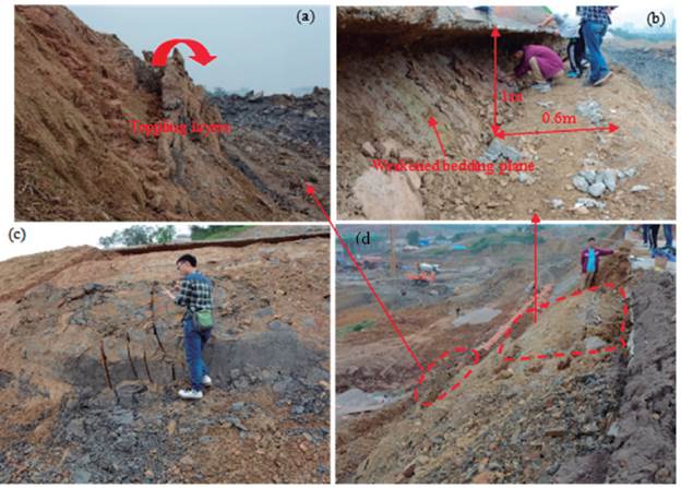
Figure 5 The complex slope failure taking place in situ. (a) toppling of the rock mass in the lower part;(b) sliding along the bedding plane in the upper part; (c) cracking of the slope face due to the push of sliding rock columns in the upper part. (d) Panoramic view of the landslide.
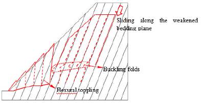
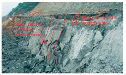
Figure 7 shows another slope failure at the study area mentioned above, the slumping block extends about 40m along the trend of the slope, with a height of 5-6m, the exposed rock mass is moderately weathered shale, the designed slope angle is 45°, while the excavated slope presents an angle of 68° which equals the dip angle of the bedding plane induced by over-excavation, under the influence of unloading, gravity and weathering, the bedded rock mass slides along the weak bedding plane, then the lower and weakened part of the layered rock mass was squeezed outward by the upper part of the slope, forming buckling folds at the toe of the slope. Consequently, the layered rock mass is fractured at the slope toe and the entire slope deforms and slides.
Based on the structural characteristics of the damaged slope, it can be inferred that the failure process of the slope involves several stages as follows:
(1) Slide-buckling deformation of the upper rock layers
The stress release perpendicular to the bedding planes make the rock mass produce spring-back towards the empty direction, consequently, the bedding planes become loose and the strength of rock mass decreases, which facilitates the sliding deformation of rock mass at the upper part along the bedding plane. For the lack ofspace at the lower sections of the slope for shearing out, buckling at the lower part occurs to coordinate with the compression from the sliding layers (Fig.7).
(2) Toppling deformation at the toe
As the buckling deformation intensifies, the rock mass at the buckling slabs becomes fragmentized and rock layers at the front is forced to rotate towards the empty space. Finally, with the development of creep deformation, toppling occurs on the rock mass in the leading edge.
(3) Connection of fracture surfaces
As buckling and toppling deformation intensifies, shale breaks and crumbles at maximum bending, then reverse sidesteps and grooves parallel to the strike of the slope generate in the leading edge, and rupture surfaces develop at the bottom of the toppling layers. Finally, the rupture surfaces connect with each other and link up with the trailing sliding surface, forming a sliding-shearing failure surface, which causes a slope failure.
Numerical analysis
UDEC numerical simulation
Numerical simulation is a useful tool for quantitative reconstruction of landslides. The distinct element code UDEC, introduced by Cundall (1987) and Lorig et al. (1991), has been widely used to model failure mechanisms of slopes such as toppling and buckling efficiently due to its ability to model large displacement and rotation along block boundaries.
The shear strength reduction technique (Dawson et al., 1999) was applied to these UDEC models to simulate the evolution of slope deformations. UDEC implements an automatic search for factor of safety using the bracketing approach, as described in Dawson et al. (1999), so UDEC solution is a dynamic, time-marching simulation. In this study, the shear strength of the joints and contacts including cohesion, friction angle in the UDEC models were reduced by the same ratio simultaneously in small increments until a FoS of 1.08 was obtained, which was indicative of the failure observed in the onsite slope. Every increment of strength reduction in the solution process corresponds to a nonequilibrium state and these nonequilibrium states at different time steps can display the progressive deformation characteristics of the slope model until the final failure. Monitoring points named A, B and C for displacement history are set at vertex position, the intermediate position and the toe of slope, respectively.
UDEC model and input parameters
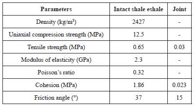
Fig.8 shows the UDEC models used in this study. The height of the slope model is 10m with a slope angle of 45°. The joints dip into the model at an angle of 68° with a joint spacing of 0.3m. To better analyze the failure mechanism of the studied slope, the simulation in the UDEC is conducted with rigid blocks and Coulomb-slip joint material model. The block densities are based on the laboratory test results shown in Table 1.
For the mechanics analysis, the surface of the slope is assigned as a free boundary, while no horizontal displacement is allowed on both the left and the right vertical boundary, the bottom boundary is completely fixed in the vertical direction but free in the tangential direction. All the boundary conditions of displacement constraint for the numerical model are rigid. In order to better describe the evolution of the slope deformation in the failure process, three displacement monitoring points named point A, point B and point C were set at the upper part, middle part, lower part of the slope model, respectively.
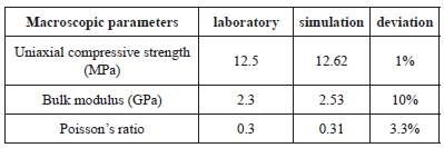
All numerical simulations by UDEC require proper selection of microparameters by means of calibration processes in which the macroscopic responses of the numerical model are compared directly to the observed responses of the physical rock material in laboratory.As macroscopic responses to be looked into, three laboratory scale macroscopic responses including UCS, Young's modulus, and Poisson's ratio were chosen in the calibration process to reproduce the strength and deformability of rock material in UDEC analyses. In this study, UDEC models of 50*100mm using various microparameters are adopted to conduct uniaxial compression simulations and an optimum set of microparameters is obtained that gives best agreement in macroscopic responses between the results from simulations and laboratory, the optimum set of microparameters is displayed in Table 2.
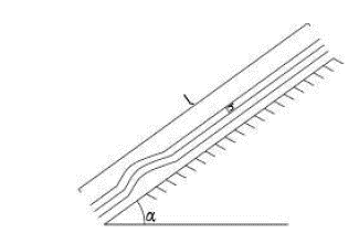
In order to ensure the veracity of DEM modeling, it is necessary to conduct back analysis of mechanical parameters of the joints according to the geological conditions from field measurement and investigation on local rock slope losing stability. Figure 9 displays the mechanical model of buckling failure.
The following analysis focuses on obtaining instability criterion of this mechanical model. According to the Euler Theory, the critical slope length lcr for buckling failure is given by
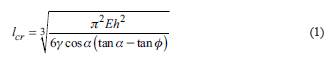
Where h is the layer thickness; E is the elasticity modulus.
After l cr is obtained, the factor of safety K can be defined in the following
Form
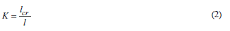
Where l is the actual slope length.
For the local slope suffering buckling failure, the bedding plane dips 68°, the actual slope length is 10.8m, the elasticity modulus E is 1500MPa, the thickness of the layered rock mass is 0.1m, when K=1.0, the equivalent friction angle of the bedding plane Φ equals 14.5°.The stability of the slope is estimated based on the limit equilibrium method, the factor of safety is 0.8 when the equivalent friction angle of the bedding plane Φ equals 14.5°, While the calculated factor of safety of the slope approximately equals 1.0 when cohesion c is 12kPa and friction angle $ is 10°, so the ultimate mechanical parameters ofjoint sets from back analysis is c=12kPa, Φ =10°.Table 3 describes the parameters for relevant materials included in the UDEC model for the rigid blocks and contacts.
Results and discussion
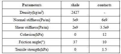
According to the simulation results, the evolution process of the deformation at different stages are shown in Figure 10. The deformation process can be divided into three stages. At the initial stage, as Figure 10a shows, obvious shearing at the trailing edge occurs, sliding of rock mass along the weak surfaces under the force of gravity can contribute to this process. Meanwhile, some shearing surfaces occur in the lower part and the toe, which can be attributed to the passive compression caused by the sliding layers from the upper part. At the medium stage, as shown in Figure 10c, buckling deformation of layers in the lower part occurs, it can be attributed to the intensifying of compression, which forces rock layers to buckle upward from the inside outwards. In addition, layers at the toe rotates under the force from the buckling layers in the rear and the layers become erect. At the final stage, more shearing surfaces occur in the buckled rock layers with the development of deformation and rock layers at the toe topple outwards (Fig. 10e), the force transformed from the buckling and shearing rock mass in the rear may contribute to this toppling deformation.
Figure 10 Plot of numerical simulation results:(a) the 2000 time step displacement contour (b) the 2000 time step velocity vector (c) the 5000 time step displacement contour(d) the 5000 timestep velocity vector (e) the 10000 time step displacement contour(f) the 10000 time step velocity vector.
To further describe the deformation process of the slope, the horizontal and vertical displacements of the monitored history points in the deformation process were analyzed, which are displayed in Figure 11. Three stages called stage I, stage II and stage III are proposed to better describe the monitoring results, which refer to the stage of elastic deformation, development of the slide-buckling deformation and the stage of toppling deformation, respectively. Clearly, the horizontal displacement of the rock mass near point A is lower than that near point B and point C in the whole deformation process, and the horizontal displacement at point A during stage I is negligible. Moreover, the horizontal displacement at point C increases more rapidly than that at point B at stage III due to the intensifying toppling at the toe where point C locates. We can see that the rock mass at the upper part where monitored point A locates moves downward in the whole process and the displacement increases more rapidly at stage III, it may be due to the intensifying toppling at the toe which provides more space for the downward sliding of the rock mass at the upper part. Moreover, increasing vertical upward displacement occurs to the rock mass at the toe where point C locates at stage I and II, and then the vertical displacement gradually becomes stable at stage III with the intensifying of toppling deformation at the toe, but the value of the vertical displacement is much lower than that at point A in the whole deformation process. It also shows that the rock mass at the lower part near the monitoring point B moves upward at stage II and then turns to moving downward at stage III, the upward displacement may be caused by the shearing force from the sliding rock mass in the upper part at stage II and the subsidence may be caused by the intensifying toppling deformation at the toe at the later stage. Comparison between the horizontal and vertical displacements at the monitored points in the deformation process indicates again that vertical displacement is dominant for the rock mass in the upper part while horizontal displacement is dominant at the toe.
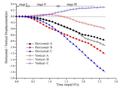
Figure 11 Displacements of the monitored history points versus numerical time steps: Stage I, Stage II and Stage III refer to the stage of elastic deformation, development of slide-buckling deformation and the stage of toppling deformation, respectively. Horizontal-A, Horizontal-B and Horizontal-C refer to the horizontal displacements at point A, point B and point C; Vertical-A, Vertical-B and Vertical-C refer to the vertical displacements at point A, point B and point C.
Conclusion
This study explored the complex failure mechanism of a shale under-dip slope based on an on-site investigation and numerical analysis. It has been proved that the under-dip slope has a complex deformation process in which sliding, buckling and toppling failure occurs sequentially at its different parts. The failure mechanism can be summarized as follows: Firstly, stress release of excavation facilitates the sliding deformation of rock mass along the weakened bedding plane, while the sliding process is hindered at the lower sections of the slope for lack of space, then rock layers move by buckling to coordinate with the compression from the upper part, when the buckling deformation develops to some degree, some fracture surface occurs at the sections of rock mass which is subjected to maximum bending effects, and the rock layers in the leading edge are forced to rotate towards the empty space, leading to toppling deformation at the toe. Finally, with the aggravation of bending and toppling deformation, fracture surfaces at the buckling folds and the toppling layers connects, then the rock mass slides along the surface gradually, which causes slope failure.
The simulating results elucidate the evolution of the complex failure for the particular soft rock slope and the findings will aid in correctly designing rock slopes with similar geological structures as the studied slope. To grasp the failure characteristics of the under-dip slope comprehensively, the influence of geological and geometrical parameters on the failure mechanism will be further studied by sensitivity analysis method in future research.

