


Serviços Personalizados
Journal
Artigo
 Inglês (pdf)
 Artigo em XML
 Referências do artigo
 Enviar este artigo por email
Indicadores
-
 Citado por SciELO
 -
 Acessos
Links relacionados
-
 Citado por Google
 -
 Similares em
SciELO
Similares em
SciELO -
 Similares em Google
Compartilhar

 Permalink
Tecciencia
versão impressa ISSN 1909-3667
Tecciencia vol.10 no.19 Bogotá jul./dez. 2015
https://doi.org/10.18180/tecciencia.2015.19.2
DOI: http://dx.doi.org/10.18180/tecciencia.2015.19.2
Compressive Sensing Hardware in 1-D Signals
Hardware de compressive sensing en señales 1D
Sergio S. Pinto1*, Luis E. Mendoza2, Hernando J. Velandia3, Valentin Molina4, Leonor J. Cervelon5
1 Universidad de Pamplona, Pamplona, Colombia, ing.sergio.elk@gmail.com
2 Universidad de Pamplona, Pamplona, Colombia, luis.mendoza@unipamplona.edu.co
3 Universidad de Pamplona, Pamplona, Colombia, hernandovelandia@gmail.com
4 Universidad ECCI, Bogotá, Colombia, amolinam@ecci.edu.co
5 Universidad de Pamplona, Pamplona, Colombia, leonor.iaimes@unipamplona.edu.co
* Corresponding Author. E-mail: ing.sergio.elk@gmail.com
How to cite: Pinto, S.; Mendoza, L.; Velandia, H.; Cervelon, L., Compressive sensing Hardware in 1-D signals, TECCIENCIA, Vol. 7 No. 19., 5-10, 2015, DOI: http://dx.doi.org/10.18180/tecciencia.2015.19.2
Received: 12 May 2015 Accepted: 5 Jun 2015 Available Online: 22 June 2015
Abstract
This paper shows the implementation in hardware of signal processing techniques known as compressive censing, compressed sensing, or compressive sampling. The CS technique works in a sparse signal space; the methods used in this article are: derived (D), discrete Fourier transform (DFT), discrete cosine transform (DCT), and discrete wavelet transform (WDT). Additionally, electronic circuits to acquire voice, electromyography, and electrocardiogram signals were implemented. Application of CS in these signals showed significant results, which promise a substantial increase in transmission speed and development of new technologies for communications in the world. Hardware implementation was performed in an FPGA (SPARTAN 3E) and a microcontroller (18F4550 PIC). The results demonstrated that it is possible to reconstruct 1D signals, breaking the Shannon-Nyquist theorem. Also, we conclude that the FPGA implementation is faster and allows higher compression ratios than with the microcontroller.
Keywords: Compressive sensing, sparse signals, compression, compressive sensing hardware.
Resumen
El presente trabajo muestra la implementación en hardware de una de las técnicas más modernas y útiles en el tratamiento de señales conocida como: Compressive Sensing (CS), sensado comprimido o muestreo compresivo. Dicha técnica, trabaja en un espacio de señales Sparse: los métodos usados en este artículo para la obtención de señales Sparse son: derivada (D), transformada discreta rápida de Fourier (TDRF), transformada discreta del coseno (TDC) y la transformada wavelet discreta (TWD). Adicionalmente, se implementaron los circuitos electrónicos para el registro de señales de voz, señales de electromiografía y electrocardiografía. La aplicación de CS en dichas señales mostró resultados significativos, que prometen un incremento sustancial de velocidades en la transmisión de información y en el desarrollo de nuevas tecnologías para las comunicaciones en el mundo. La implementación en hardware se realizó en una FPGA (SPARTAN 3E) y en un microcontrolador (PIC 18F4550). Los resultados obtenidos demostraron que es posible reconstruir señales 1D, rompiendo el teorema de Shannon y Nyquist. Así mismo, se llegó a la conclusión de que la implementación en FPGA es más rápida y permite porcentajes de compresión más elevados que con el microcontrolador.
Palabras claves: Sensado compresivo, señales sparse, compresión, hardware compressive sensing.
1. Introduction
All communication signal treatment systems have to need to consume the least possible amount of resources. A system is considered efficient and competent if it uses the least amount of resources to obtain better results. Due to this diverse techniques of information transformation, analysis, and compression emerge, which permit improving system performance. Compressive sensing (CS) is one of these techniques that permits reconstructing a signal with few samples. Also, the Shannon-Nyquist sampling theorem establishes that for the perfect reconstruction of the signal it is necessary to take samples by using a rate of at least double the bandwidth [1]. The new compressive sampling theory or CS explains that under specific conditions a sparse signal can be reconstructed by using a small number of samples, obtained from a random subsampling, in such a way that it is possible to say that in CS the number of samples is lower than that required for the Shannon-Nyquist theorem [2].
Compressive sensing is a recent signal processing field; according to Candes, Romberg, and Tao results [3] and Donoho [4], is a way of acquiring compressible signals (scarce). In CS, the quality of the reconstruction depends on signal compressibility, election of a reconstruction algorithm, sparse transformation method, and random sampling [5]. Currently, different sparse transformation methods exist depending on the signal information [6]. The most-used methods include: discrete cosine transform and wavelet transform. This article shows the results of compression/reconstruction with CS on voice, electromyography, and electrocardiographic signals by applying conversion methods like: D, DCT, FT, and TW.
Applying the sampling theorem sometimes implies high acquisition of data, generating losses in computational costs, given that compression is an obligatory step in themes like data storage or transmission [7]. The aforementioned explains that additional information requires a higher number of samples and, hence, a better compression technique. For example, digital cameras include an increasingly higher number of megapixels (these are millions of sensors that take samples), all the data acquired are discarded by the compression algorithm within (in general, JPEG or JPEG 2000), which produces the photograph that is finally observed in the camera [8].
To solve these types of repercussions, it is necessary to think beyond the Shannon-Nyquist theorem. Thus, CS can be a useful tool. The work by Richard Baraniuk and Kevin Kelly, from Rice University, shows a camera with only one pixel that works with CS and reduces the number of samples taken to acquire an image [6]. The word sparse may mean something poor, scarce, limited, short, and distributed, but in the context of signals, sparse does not mean few data; it is a signal whose majority of values are zero or of small amplitude, and some points or few points of the signal are of high amplitude. [9]. The signal is high density compressible if it has a large number of separate low peaks or of low density if it has some high separated peaks. Finally, this work makes a novel contribution in the implementation of CS in hardware and its validation with voice, electromyography, and electrocardiographic signals. The vast majority of works presented in this area are limited in software implementations, which makes this article a starting point for the implementation of CS in hardware.
1.1. Compressive sensing
The high compressibility of CS is due to the way the samples are taken; the number of M samples is a function of the amount of the K-sparse values (point different from zero in amplitude) the signal has, the vector measurement, and of an x signal having a length of M samples. In fact, CS is capable of sampling sparse signal by using smaller measurements than those required by the Shannon-Nyquist theorem. The minimum value of M is double the K-sparse points E in the signal, so that M>K<< N, in such a way that by using M>3K optimum reconstruction is guaranteed; the measurements are made of a subsampling of the values of the x signal. To explain this, we defined a vector x ∈ R, with N length, which means that screen scarce x signal with zero values and non-zero K values. Mathematically, CS is defined in "(1)", [7], and [10].

Each Si (i = 1, 2... N) value in "(1)" may be obtained from the product ψiTx; T indicates the transposed, that is, that a sparse signal can be reconstructed. The sampling of x is carried out without taking N measurements. This is what CS represents in a compressed sampling, done from a few measurements; the result of this operation is stored in a y vector with the aid of random Φ bases. Measurements are now made by computing the internal product between the x signal and a Φi vector arrangement, whose result is defined as yi; the Φ base is also known as coding base, designed to facilitate the reconstruction of a sparse signal. Φ has dimensions N x M, so that the y vector is defined as shown by the following:

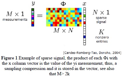
The prior equation shows how from the x vector and the Φ matrix, with N x M size, we may obtain a y compressed vector, with M dimension [4]. Within y we find implicit operation/combination products like the K-sparse values of the x signal. The compression range during the sampling is controlled by the user, in conformity with the M value, the rows of the coding base; testing M values in different dispersed signals will permit finding the optimum balance between a very high compression and a good reconstruction, an image that explains the acquisition of the measurements is shown in Figure 1[7].
The reconstruction process is a complex task, which implies using the base and the y coding vector, to reconstruct the original x signal. If N is the number of measurements capable of constructing a system of equations with only one solution, but since M << N the possible solutions are many (expressed as x* that would be the solution vector). The situations complex because there is only one single solution (the original x vector). A common analogy to explain this is the game of Sudoku; the solution in a Sudoku entails finding an answer through a large field of possibilities, which dismisses candidates using some type of property, pattern, or norm. In this case, the rule is that the number cannot be repeated in any row or column of the 3x3 square. Similarly, in CS it is necessary to use a rule to dismiss solutions that satisfied equation (3):

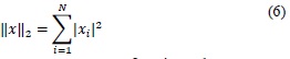
An effective way of doing this is through the norm, a vector property defined by the linear algebra in the following manner [11] :
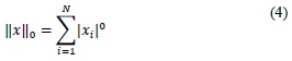
Lo norm of vector x
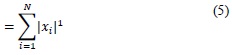
L1 norm of vector x:
L2 norm of vector x:
Currently, there are many ways of using the norm to dismiss possible x* solutions and discover the value and the position of each K significant point in the x vector; equation (4) induces that 00 = 0 and equation (5) is a way of reconstructing the x values of the vector [6]. The L1 norm is now a linear optimization problem. The aim of this problem is to find an x* with the smallest L1 norm (Equation (5)). Given that in each x* the K-significant values are combined and supposes that x* satisfies equation (5), with a small L1 norm is quite likely the desired solution (in these cases the L1 value and the L0 value of the vector are similar) [6]. This is expressed mathematically as:

This is the principal premise of L1 minimization, a reconstruction method, S' in equation (7) is called reconstruction of x (or the vector solution) and S' is the denomination for all the possible x* vectors. Regarding signal construction, the procedure known as L1 Magic, or L1 minimization is one of the most-used procedures, given that it is a very efficient algorithm for CS applications. In this work, tests were based on L1 minimization [12]
2. Methodology
During the development of this research, voice, electromyographic (EMG), and electrocardiographic (ECG) signals were registered. To acquire ECG and EMG signals, the instrumentation amplifier (INA 115) was used; thereafter, this was converted into sparse and the compression process was carried out. The compressed signal was sent to a computer, where the reconstruction process was applied, to verify the robustness of CS in each of the signals. Compressed sensing has had big progress and significant results in. However, this technique still does not have important accomplishments at hardware level. This motivated performing the physical implementation that would suggest a solution in real time. For the implementation in real time tests were rum with different programmable logical devices, obtaining satisfactory results with an FPGA (SPARTAN 3E) and with a microcontroller (PIC18F4550). For both cases, capture of analogue signal and conversion to digital signal was carried out by using the microcontroller's A/D converter; likewise, this was used to send the compressed signal to the computer via USB port and, thus, decompression and analysis was conducted.
2.1 Signal conversion to sparse
The methodology applied to convert signals to sparse is shown ahead. Four methodologies were applied. The derived (D), the discrete fast Fourier transform (DFFT), the discrete cosine transform (DCT), and the discrete wavelet transform (DWT). For the derived method (Equation 6), x represents the original signal, the y vector is the derived signal, and N is the signal length [9].

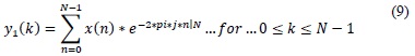
For the application of the discrete fast Fourier transform (DFFT), y1 presents the frequency components of the original signal [13].
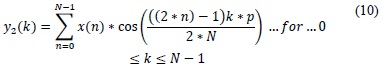
The discrete cosine transform (DCT) was applied by following equation 9, where y2 represents the DCT coefficients [14].
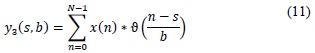
Finally, discrete wavelet transform (DWT) was applied, where y3 are the wavelet coefficient, s is the displacement coefficient, b is the scaling coefficient, and  is the mother wavelet [15].
2.2 Implementation with microcontroller
To apply CS using microcontroller, segments of 10 samples of the input signal were acquired, along with an output of six elements. That is, 40% compression. This decision was made to observe the system's rapid response [16]. Initially, the USB port configuration was performed. The random matrix implemented has a size of 6(rows)*10(columns). It is worth mentioning that during the software stage the same random matrix in the hardware must be stored, this is for the purpose of achieving a successful reconstruction. To perform the respective tests, 8000 analogous samples were taken of the signal (voice, ECG, or EMG), so that 800 segments were processed. As previously mentioned, the reconstructed values are within a sparse space. Consequently, the inverse process was conducted for signal decompression. Four methodologies were applied for this: inverse derived (ID), inverse Fourier transform (IFT), inverse discrete cosine transform (IDCT), and inverse wavelet transform (IWT). Thereafter and to obtain the data in the original space, the inverse process was performed during the signal pre-conditioning stage. For this case, a subtraction was performed with a constant 2.5-volt value. Lastly, the data concatenation process was performed to obtain the 8000 length vector.
2.3 Implementation with FPGA
The Spartan 3E FPGA card has a vast amount of characteristics that make it superior to microcontrollers, starting with its memory and speed [17]. The programming was implemented on the Xilinx Ise program. Here, 160 segments from 50 positions were taken. That is, 50 possible values of n and 50 possible values of k. Then, we have a total of 50*50 = 2,500 possible combinations. To implement the random matrix, a similar 50x50 signal was used. These values were introduced to the program through a table of 2500 data in a type 3 vector signal, which is an arrangement from 0 to 2500 and which contains integer values in the range from -10000 to 10000. The whole process is carried out in a single work cycle of the FPGA card. This permits a big advantage for this device, which surely will be one of the best alternatives for the application of this novel hardware technique. Synthetization of the process in the FPGA lasted approximately six hours. The compressed data is sent via USB to the computer to be reconstructed with the L1 method and compared to the original signal.
3. Results
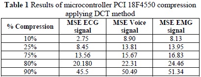
Table 1 shows the results obtained from the reconstruction by using microcontroller PIC18F4550 and DCT as conversion technique. To show reconstruction error, portions of original signals are compared to the reconstructed signal. The mean squared error (MSE) was calculated between said signal portions, revealing how the best results were obtained by using the ECG signal; also, note that with greater compression there is greater loss of information.
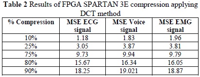
Likewise, Table 2 shows the equivalent results regarding the implementation of CS in FPGA and DCT as conversion technique. Note how the results using FPGA present less MSE than those obtained with PIC18F4550 and present a coincidence in that the ECG signal has the best signal performance.
Also and to consolidate the results obtained, Figure 2 shows the results of the MSE values for different compression percentages and the conversion techniques to sparse, like FT, D, and TW, for the voice signal. Observe how the TW technique permits obtaining more adequate reconstructions tan those obtained with D and FT. Also note how the best results are obtained by using FPGA, given that for example: for a compression percentage of 10% an MSE of 9.03 id obtained if a microcontroller is used and if an FPGA is used the MSE is 6.02.
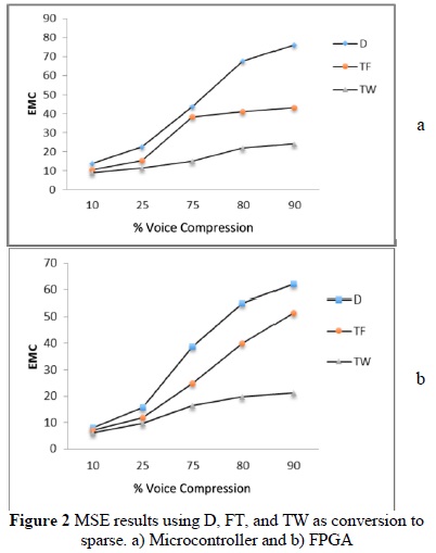
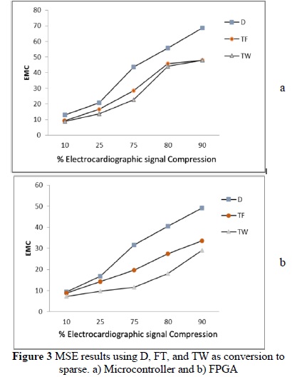
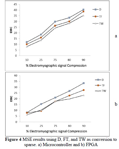
Figure 3 and Figure 4 show analogy with Figure 2; it is the same procedure, but for ECG and EMG signals, respectively. From these graphics it may be observed how the best operation of the system is maintained if an FPGA is used, as well as TW as conversion technique. The derived method is not the adequate tool for this type of procedure; it presents high MSE compared to the other techniques, as shown in Figure 3. Using D, we obtained an MSE equal to 68.69 for an electrocardiographic signal compression of 90% in microcontroller and 49.21 in FPGA. This error is much higher than that obtained through the Fourier transform (FT) method and the wavelet transform method, whose errors were close to 48.02 and 47.91, respectively, in microcontroller and 33.58 and 29.01, respectively, in FPGA. For this reason, it is possible to identify that the derived method is not the most adequate for signal compression.
Finally and comparing among Figure 2, Figure 3 and Figure 4 and Table 1 and Table 2, it may be stated that the best conversion technique is DCT and the FPGA is the recommended hardware. For this work, tests were performed on 35 ECG, 35 EMG, and 35 voice signals.
4. Conclusions
Compressive sensing is a mathematical technique that permits reconstructing signals without complying with the Shannon and Nyquist theorem, thus, in the future this technique will certainly revolutionize telecommunications, which is one of the areas that benefits most from data compression. Currently, CS is being tested in areas like Biology, Geology, Telecommunications, and Imaging. This work demonstrated that CS functions adequately in the field of physiological signals like voice, ECG, and EMG, depending on what is sought in the application. Also, for good operation of CS, a suitable technique needs to be selected to transform data to sparse; this work demonstrated that the best technique for physiological data is DCT, given that it creates an ideal sparse space for the CS requirement. The other techniques, although functional, do not permit - upon signal reconstruction -obtaining responses similar to the original signal. Regarding the system's velocity in applying CS and delivering information, the best system conducted in this work was FPGA, given that it took up less time and the results were more adequate; this is because signal portions were taken from 50 points and with the microcontroller only signal portions with 6-point length were taken. It is concluded that it is best to take great length frames to apply CS. Additionally, voice signals may be correctly reconstructed after being compressed at a maximum compression rate of 72% in FPGA and 30% in microcontroller. The ECG signals can only be reconstructed correctly if these are compressed at a maximum sampling rate of 40% in FPGA and 10% in microcontrollers. Likewise, the maximum compression rate that can be applied in EMG signals is of 10%. This is because these last signals require greater precision, given that small alterations in their characteristics may lead to wrong diagnoses. Lastly, it is considered that CS can be used as robust coding technique because for its reconstruction optimization algorithm is needed to find the ideal system response.
References
[1] P. D. O' Grady y R. Schott T., «Compressive sampling of non-negative signals,» de Machine Learning for Signal Processing, 2008. MLSP 2008. IEEE Workshop on, Cancun, 2008. [ Links ]
[2] M. Salman Asif y J. Romberg, «Dynamic Updating for '1 Minimization,» IEEE Journal of Selected Topics in Signal Processing, vol. 4, n° 2, pp. 421-434, 2009. [ Links ]
[3] E. J. Cades, J. Romberg y T. Tao, «Robust uncertainty principles: exact signal reconstruction from highly incomplete frequency information,» IEEE Transactions on Information Theory, vol. 52, n° 2, pp. 489-509, 2006. [ Links ]
[4] D. L. Donoho, «Compressed Sensing.» IEEE Transactions of information theory, vol. 52. n° 4. pp. 1289-1306. 2006. [ Links ]
[5] P. T. Boufounos y R. G. Baraniuk. «1 -Bit compressive sensing.» de Information Sciences and Systems, 2008. CISS 2008. 42nd Annual Conference on. Princeton. 2008. [ Links ]
[6] D. Mackenzie. What's happening in the mathematical Sciences. American Mathematical society . 2009. [ Links ]
[7] W. Barakat. R. Saliba y B. Evans. «Compressive Sensing for Multimedia communications in wireless sensor networks.» MDDSP. 2008. [ Links ]
[8] B. Hayes. «The Best Bits-A new technology called compressive sensing slims down data at the source.» American Scientist, vol. 97. n° 4. p. 276. 2009. [ Links ]
[9] L. Meriño y L. E. Mendoza. «Estudio y aplicaciones de la tecnica compressive sensing en señales sparse.» Tesis- ingenieria en telecomunicaciones- Universidad de Pamplona. 2009. [ Links ]
[10] R. Baraniuk. «Compressive sensing.» IEEE signal Processing magazine, vol. 24. pp. 1-9. 2007. [ Links ]
[11] P. Boufounus. J. Romberg y R. Braniuk. Compressive Sensig: Theory and applications. 2008. [ Links ]
[12] «l-magic.» 2009. [En línea]. Available: http://statweb.stanford.edu/~candes/l1magic/. [ Links ]
[13] S. Aldirmaz y L. Durak-Ata, «Compressive Sensing of Linear Frequency Modulated Signals in Fractional Fourier Domains,» de Signal Processing and Communications Applications (SIU), 2011 IEEE 19th Conference on, Antalya, 2011. [ Links ]
[14] Q. Wang y W. T. J. Zeng, «Compressive sensing based secure multiparty privacy preserving framework for collaborative data-mining and signal processing,» de IEEE International Conference on Multimedia and Expo (ICME), Chengdu, 2014. [ Links ]
[15] X. Qian, X. Hou, L. Zhang, C. Gong, L. Xiao y J. Sun, «SAR image Bayesian compressive sensing exploiting the interscale and intrascale dependencies in directional lifting wavelet transform domain,» Journal Neurocomputing, vol. 133, n° 10, pp. 358-368, 2014. [ Links ]
[16] J. L. Stanislaus y T. Mohsenin, «Low-complexity FPGA implementation of compressive sensing reconstruction,» de International Conference on computing, Networking and Communications (ICNC), San Diego, 2013. [ Links ]
[17] K. Karakus y H. A. Iligin, «Implementation of image reconstruction algorithm using compressive sensing in FPGA,» de 20th Signal Processing and Communications Applications Conference (SIU), Mugla, 2012. [ Links ]
