


 English (pdf)
 Article in xml format
 Article references
 Send this article by e-mail
 Cited by SciELO
  Cited by Google
  Similars in
SciELO
Similars in
SciELO  Similars in Google
 Permalink
1. Introduction
Currently, use of radar sensors in civilian and military settings has gained acceptance due to two main reasons: first, given that radars are ‘full-time’ sensors, they have the advantage over other sensors of operating adequately independent of the environmental conditions of the setting. For example, in cases of fog, an optronic sensor would have a limited field of vision. Secondly, due to the miniaturization of electronic components, the current market offers smaller and lighter units or devices, easy to manipulate and at low cost, known as commercial off-the-shelf elements (COTS). These components have triggered the development of low-cost, portable electronic sensors with short development times
This article shows a frequency-modulated continuous-wave (FMCW) radar system developed from COTS elements, which has as central component the K-LC6 transceiver module made by “RFbeam Microwave GmbH” [1].
Frequency-modulated continuous-wave radars have diverse applications, such as radio altimetry, liquid level meters, navigation radars, vehicle anti-collision systems, precision measurements of distance from targets, small motion measurements, among others [2].
Some companies, like Siver Sima, Sonicelectronics, RFbeam, Whistler, and Beltronics are among those dedicated to manufacturing low-cost radars, with prices even below 200 US Dollars [3], offering diverse applications in automation, medicine, and security among others.
The following sections describe the development and tests of said radar system. As a result, an FMCW radar prototype was obtained to measure speed and distance to a target.
2. Methods
2.1 System Description
2.1.1 System Architecture
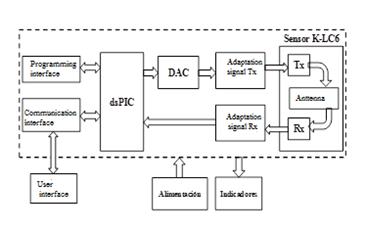
Development of the radar system stems from the reference framework shown in Figure 1. The sensor is comprised of hardware (HW) and software (SW), which jointly provide the system the capacity to measure radial speed and distance of the radar to a target through an FMCW signal. This measurement is indirect, given that the target echo signal is processed digitally, which is used to calculate each parameter mentioned.
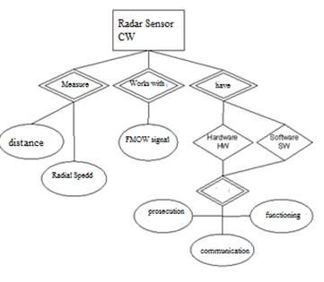
According to Figure 1 both the HW part and the SW part of the system carry out similar tasks of processing, communication, and operation:
The HW corresponding to the printed circuit board (PCB) and electronic components of the whole system is in charge of operating the system’s circuits, antennas, and filters among others. It is also in charge of performing the first part of processing the information from the target, that is, receive the echo from the signal reflected by the target, adapt, digitize, format, and send it to the computer via USB.
The SW is in charge of processing the signal. A part of the processing takes place on the card’s DSP and the other on a computer. The computer receives the data signal via USB and organizes it for processing; it then proceeds to calculate the distance and speed of the target to, finally, visualize this information.
A general block diagram of the radar system is shown in Figure 2. This radar works with FMCW signal that by using the Doppler Effect permits indirect measurement of speed and distance [4].
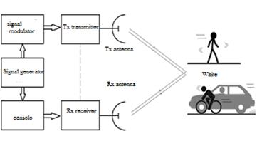
Processing the signal received permits establishing the presence and distance for fixed targets and, additionally, the speed direction of the motion with respect to the radar for moving targets.
2.1.2 Measurement of distance and radial speed
The FMCW signal transmitted is a train of signals modulated linearly in frequency with a determined PRI period. When reaching the target, part of it is reflected and returns attenuated with a certain delay toward the radar receptor. There, it mixes with the signal transmitted to obtain the beat frequency, given by:
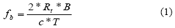
Where B is the sweep bandwidth, T is the sweep time, c the propagation speed of the waves in the medium, and Rt the distance travelled by the signal. Solving for Rt in (1), the distance from the target to the radar can be calculated.
This work implemented a filter bank to measure distance. Said filter bank shows the signal received and performs a discrete Fourier transform (DFT) in quick time (Inter-ramp: inversely related to the sampling frequency of the signals; the DFT is performed along the samples from each ramp [5]), which determines the beat frequency to calculate the distance.
To measure the speed of the target with respect to the radar, a second calculation is made. Herein, the Doppler frequency is estimated due to phase change undergone by the beat signal along a series of ramps of the FMCW signal, considering the null intra-pulse movement [6]. The variation in the ramp-to-ramp phase is almost linear in slow time (Inter-ramps: the DFT now occurs along each ramp in the distances profile obtained previously [5]), so that a sinusoid of constant frequency is produced. This sinusoid is proportional to the radial speed of the target (Doppler frequency) vr , given by:
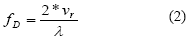
Finally, solving for vr in the previous equation, the radial speed of the target with respect to the radar can be calculated.
2.2 System Development
2.2.1 Hardware: System Board
The block diagram of the elements comprising the system board is shown in Figure 3.
As already indicated, the radar system stems from the transceiver K-LC6 module, which integrates in the same unit the antenna, signal transmitter, and signal receptor.
To achieve an FMCW signal in transmission, this module must be powered with an analog ramp signal conditioned to the voltage levels required and with the working frequency desired.
In reception, this circuit demodulates the signal received and delivers it in intermediate frequency through the I/Q channels in analog form, making it necessary to condition and digitize it for its subsequent delivery to the DSP to format and deliver it to the computer. In this case, the computer is the user interface, but a port is also available to have the graphic interface through a liquid crystal display (LCD) in the future.
The system’s board is controlled by a DSP, in this case, a dsPIC® by Microchip®[7]. The board has a power source, communication ports, LED indicators, and complementary elements for the correct operation of the radar system.
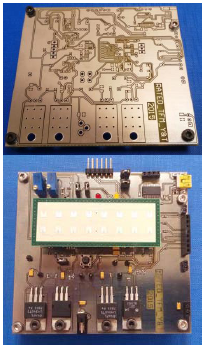
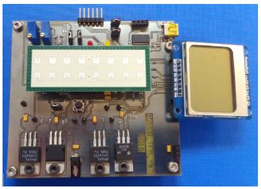
The PCB and the assembled circuit are shown in Figure 4.
2.2.2 Software modules
Two different algorithms were developed to take care of the tasks of signal and data processing: one in the board’s dsPIC® and the other in the computer.
2.2.2.1 dsPIC® program
This program is in charge of running the following tasks (Figure 5):
Programming interface with PicKitTM3.
Generate the discrete signal to construct the ramp that powers the K-LC6 module.
Read the I/Q analog input signals, digitize and format them.
Send the digitized I/Q signals through a universal asynchronous receiver-transmitter (UART) protocol to the USB interface to communicate with the computer.
Turn the LEDs on or off to indicate system operation.
Monitor the RESET signal to restart system operation.
P2.2.2.2. Program for computer data processing
We used MATLAB® in this work because of its robustness to manage mathematical operations with data matrices.
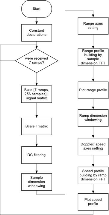
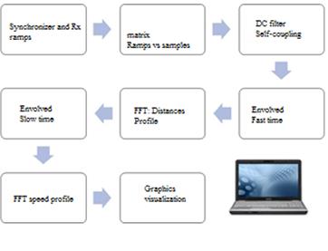
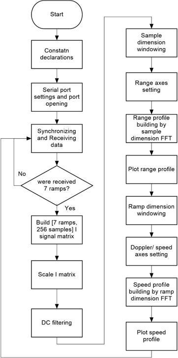
Upon digitizing the signals in the dsPIC®, these are also placed in a format of data vectors for each echo received, which are then organized in the computer to be processed in matrix form, speeding up the mathematical calculations. This seeks to show the data in the user interface with a real time sense. Figure 6 and Figure 7 show the principal blocks of the algorithm in MatLab®, and the flow diagram, respectively.
2.2.2 System integration
Prior to the integration, each of the blocks of the system was tested and adjusted, as required, by following the test protocol indicated ahead. Once these tests were performed to conformity, the respective connection of HW and SW elements was conducted to finally make the measurements and adjustments of the whole system.
2.3 Test protocol
This protocol integrates the tests indicated in Table I. The tests were iterative and were carried out progressively as conformity was obtained with the development and operation of each element, until testing the complete system. The types of tests consist in:
INS: Conduct an inspection or visual exam to test the track design, location, and type of HW element (for example, manufacturer reference) among others.
MED: Measure parameters by using laboratory equipment with multimeters or oscilloscopes, to test the electric signals of element operation.
FUN: Test operation of any equipment or element, using laboratory equipment to generate input signals and read output signals.
ANL: Make necessary theoretical analyses, according to the signal theory or radar theory to test and/or validate the measurements made by the system. This analysis includes the use of computer tools.
2.4 Applications
During development of the project, by revising some sources of information, it was found that these types of small, portable sensors are adequate in applications in the following fields:
- At urban level, to monitor pedestrians and drivers, seeking their safety in road mobility.
- Biometric, to measure parameters in people, like body movement, blinking, chest movement, among others. For example, to identify people and control access to restricted areas in a building.
- Medical, to monitor said biometric signals. For example, these sensors can be used to establish an automobile driver’s level of fatigue to avoid traffic accidents.
- Domotics (home automation), for vital sign surveillance systems, to care for the elderly or individuals with some motor difficulty, who are at home most of the time, to open doors automatically with presence sensors, among other examples.
- Navigation control, for unmanned vehicles.
- Vehicular, in intelligent vehicles with sensor networks for parking assistance
3. Results
The following describe the results obtained in the tests for distance and speed. These tests used a scenario with fixed and moving targets. The moving targets were people approaching and moving away from the radar and who were carrying different elements to vary their radar section. The place for the tests was a building hallway with other elements, like doors and metallic tables serving as fixed targets. Objects of different sizes and materials were also used and these were placed or moved along the hallway as the tests advanced. Figure 8 shows a representation of the scenario and a photograph of the test assembly.
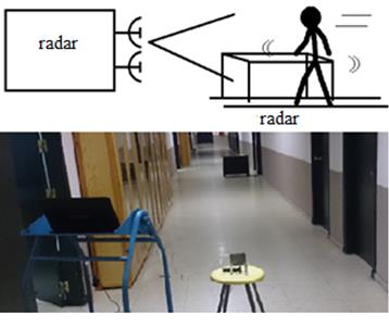
Figure 8 Test scenario. Assembly of the radar system with computer display of the data of speed and distance.
3.1 Distance Range
Upon confirming the operation of the system’s board, it was connected to the power source to verify that the reception signal’s adaptation stage was not saturated.
This implies loss of information from the target’s echo - as noted in Figure 9. The circuit has control son the reception stage to calibrate manually the signal gain in case of saturation. Upon calibrating the signals, we obtain the distance profile shown in Figure 10.
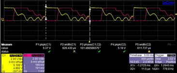
Figure 9 I/Q signals (yellow and red). On the oscilloscope, the flat zone on the left side of each signal indicates saturation of the adaptation amplifiers.
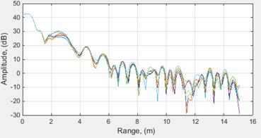
Figure 10 Distance profile. Amplitude (dB) of the echo received in function of the distance at which the target is placed.
Figure 10 illustrates that distance zero has a large lobe, which should not be interpreted as a target. This lobe appears because the coupling of the signal transmitted in the receptor, a typical characteristic of CW radars [8]. In the distance of 2.5 m, approximately, it is possible to distinguish a target corresponding to the building’s ceiling.
It is worth highlighting that calibration of the amplifiers is not automatic, but manual, meaning that to observe detections at greater distance, it is necessary to saturate the amplifiers for nearby distances. The contrary also occurs: when calibrating the amplifiers to see targets nearby, remote targets arrive without much gain and their detection may be difficult.
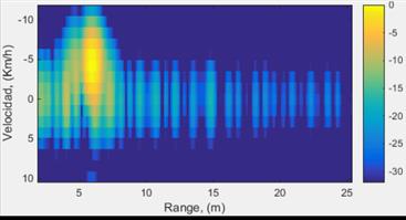
3.2 Speed
This test was conducted using the same principles described in the section above.
Table 2 Technical characteristics of the radar system
| No. | Item | Value | Unit |
| Frequency of transmission | 24.15 | GHz | |
| Bandwidth | 270 | MHZ | |
| Range | 0.6 to 63 | m | |
| Resolution in distance, (R | 0.56 | m | |
| Doppler resolution, ( fd | 138.89 | Hz | |
| Resolution in speed | 3.09 | km/h | |
| Maximum Doppler Frequency Not ambiguous | 416.67 | Hz | |
| Maximum speed Not ambiguous | 9.28 | km/h |
In this case, it is important to distinguish when a target is approaching and when it is moving away from the radar (Figure 11). We want to emphasize the role played by the gain control during the reception stage and the presence of the lobe due to the coupling of the signal transmitted in the receptor.
4. Conclusions
The system developed is an FMCW radar prototype, constructed with commercially available low-cost elements, which is less than 100 € estimated in materials and technical manufacturing services, with low power consumption, and small in size and volume.
This prototype used MatLab as processing and visualization tool to test the radar’s operation. However, the hardware manufactured was designed to work jointly with a dsPIC® of higher features (RAM memory) for the signal processing without need for a computer, and has an interface to connect an LCD display, so it works independently from MatLab (Figure 12).
Commercial elements, like the K-LC6 transceiver have advantages and disadvantages to consider in the design or development of any system. This case considered the advantage of integrating in a single unit the transmitter, receptor, and antennas for a continuous wave (CW) radar, saving time in the development of these elements and permitting to center the design on the HW board and on signal processing.
A disadvantage is that because the transceiver is a closed system, it does not permit modifications in case of requiring any improvement; for example, isolating between the transmitter and receptor, which is key in CW radars.

