Inglês (pdf)
 Artigo em XML
 Referências do artigo
 Enviar este artigo por email
 Citado por SciELO
  Citado por Google
  Similares em
SciELO
Similares em
SciELO  Similares em Google
 Permalink
1. Introduction
The world is facing the great challenge of our time: to reach net zero by 2050 and limit the rise of global temperature to 1.5 °C. This requires, without further ado, a total transformation of energy systems. This definitely requires a total transformation of energy systems [1]. Indeed, energy is a critical economic and environmental development challenge that the world continues to face today [2].
Hydropower is a flexible, lowfiemissions source of generation [1] and gives a significant contribution to the world energy demand with 4, 370 TW h electricity generated in 2020 [3]. Historically, it is associated with centralised generation based on big power plants [4,5] with significant advantages, but also with no less significant disadvantages [6,7]. Nowadays, energy generation is increasingly distributed [8] with great advantages, mainly when associated with microgrids [9-12].
Small-scale hydropower generation can be a fundamental foundation for sustainable development, public service delivery, as well as poverty alleviation. Despite the appeal and benefits of small-scale plants, 66% of their potential around the world remains untapped [3].
In the new paradigm of distributed generation and self-consumption, the integration of small and very-small hydro systems in the local context, through the optimized use of water resources, can positively impact on the local ecosystem [4,13,14]. These small systems, up to 5 kW [6,7,15] or 10 kW [4], are mentioned in the literature as pico-hydro systems.
When integrated into existing infrastructures, their impact is twofold: renewable electricity generation and the spread of small-scale hydro systems. In such applications, where electricity generation is not the main priority, those systems are designated as multipurpose schemes [13]. Thus, while the existing infrastructures continue to guarantee their primary function, they also generate energy at the same time. Water supply systems, irrigation channels and wastewater treatment systems are just a few examples [4,16,17]. Under this purpose, this paper presents a pico-hydro system suitably integrated into existing infrastructure, which consists of using the water discharge for a tank at the Centro Aquícola de Castrelos (Castrelos’ Aquaculture Centre), in Bragança, Portugal [18]. This work was carried out under the project BIOURB-NATUR - Bio constructive diversity, bioclimatic building, sustainable rehabilitation and application in natural parks, funded by European Commission - POCTEP.
During the last decades, small-scale water turbines have been used in off-grid pico-hydro systems in rural areas [14,19] and some works present new developments for improved quality [20]. Recently, the development of these systems has gained new impetus through its use in new applications, such as: in hybrid systems with pumped-hydro energy storage [21] , in microgrids for energy storage [22], or as a cost-effective and well-established way to generate electricity [9].
In fact, there is a wide use of pico-hydro systems, especially in off-grid systems, which are very popular in developing countries [4,14,23,24]. However, despite the trigger of emerging applications, there are still knowledge gaps regarding the most effective approach for connecting them to the grid, which is one of the goals of the study presented in this work.
Recently, studies have been published based on two distinct approaches. The first consists of the development of specific control for the power electronics responsible for the generator operating point and grid interface [8,10]. The second uses a more effective solution. This latter approach is based on the “plug and play” principle, with the integration of technology widely available on the market and at very competitive prices [25,26].
This paper is intended as a relevant contribution to this second strategy. It is based on the proper integration of a permanent magnet synchronous generator (PMSG), widely used in small wind turbines [11,27], and photovoltaic (PV) string inverters. In general, an over-voltage protection circuit is additionally required [28].
Water turbines used to generate electricity are a mature and widely spread technology, even for small hydropower plants [10,23,24]. In ancient times, more than 2000 years ago, waterwheels were an important discovery as hydraulic machines used to convert water energy into mechanical energy. They were extensively used for many centuries, in many applications, until they were replaced by the electric motor in the middle of the last century [29,30]. Water turbines were considered a relic from the beginning of the industrial revolution [29].
During the last decades, due to new societal challenges related to environmental sustainability, the need to explore low head hydroelectric power sources to generate electricity became greater than ever [29]. Nowadays, waterwheels have become attractive again as water turbines for power generation. This happens not only where large distances usually require decentralized electricity production, and off-grid power plants, but also as a grid-connected system [10,22,25].
Waterwheels are environmentally friendly and can help preserve cultural heritage [30], such as in the Silk House museum, where a waterwheel was installed in the place there was a former mill [31]. Moreover, they can contribute to the promotion of eco-tourism and social activities [30,31], as in the present case of the BIOURB-NATUR project[18].
Most of the knowledge about waterwheels is very old, and there is a lack of information and uncertainty [32]. Therefore, several recent studies have been carried out to evaluate their performance and efficiency improvements [30,32,33], even for power ranges of just a few hundred watts [16].
Despite this recent interest in small-scale turbines, including waterwheels, there is still another challenge: how to connect to the grid in a cost-effective, robust and flexible way. This paper is an extended version of the work presented in [18] and is intended as an important contribution to this challenge. It proposes an effective (robust, flexible, efficient, economical and practical) grid connection approach, applied to an overshot waterwheel, which is based on inverters and generators widely available on the market.
The paper is organized as follows: after this introduction, the design of a waterwheel using a freely available tool [34,35] is presented in section 2; the content of section 3 is intended as a relevant contribution to the state-of-the-art and presents the detailed design of an effective grid connection approach based on widely available components; section 4 presents the implementation details and experimental results; and section 5 presents the results and their analysis. Finally, the conclusions are presented in section 6.
2. Overshot waterwheel
Among all kinds of waterwheels, the overshot one presents the highest efficiency (up to 85-90%) over a wide range of water flows [33]. The overshot waterwheel is generally used for head differences of 2.5 − 10 m, and flow rates of 100 − 200 l/s per metre width [29]. Unfortunately, the site conditions for implementing an overshot waterwheel at the Castrelos Aquaculture Centre do not completely satisfy the ideal site parameters. Indeed, the main channel that captures the water from the river has a flow of approximately 100 l/s and the heads that can be exploited are low (less than 2.5 m).
After interviewing the people working at the Aquaculture Centre, and in order to suitably integrate the waterwheel into the existing infrastructures, it was designed to take advantage of the water falling into a tank.
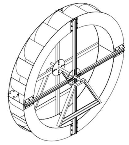
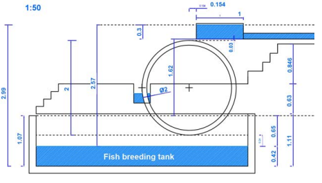
The highest head available was 2.5 m and the flow rate was about 15 l/s by the time of the data survey. Considering the efficiency of these waterwheels is approximately constant over a wide range of flow rates [29,33], it was decided to design a wheel for 25 l/s with a diameter of 2 m. There are some recent works related to the design of waterwheels, namely the overshot type [32,33,35]. In this work, the platform available online [34] and the master’s thesis [35] were used. Figure 1 shows a draw of the designed overshot waterwheel, and Figure 2 shows the implantation scheme in the fish breeding tank. The waterwheel was built in stainless steel with 4 radial arms, 26 cm width and a total of 20 buckets 26 cm length, 20 cm depth and 31.4 cm width and spacing. The estimated rotational speed, at maximum power, is 6.8 rpm.
The estimated hydraulic power depends on the design water flow (25 l/s) and the head available (2 m) on the site. The generated mechanical power P (W) at the turbine shaft is estimated by Equation (1), as follows [36]:

where η is the turbine hydraulic efficiency, g is the acceleration due to gravity (≃ 9.8 m/s2 ), ρ is the water density (= 1000 kg/m 3 ), Q is the water flow in the turbine (m 3/s), and H is the gross head (m). Considering g ≃ 10 m/s2 and the water flow expressed in l/s, the mechanical power equation can be simplified by Equation (2), as follows:

Assuming an overall efficiency (including waterwheel, gearbox, generator, cable, rectifier, and inverter) of 50%, the power injected into the grid will be 5 × 25 l/s × 2 m = 250 W.
3. Grid connection approach
Nowadays, the grid connection of small wind turbines and PV modules is a mature technology and spread worldwide [11,37]. Therefore, PMSGs and PV inverters are widely available and at competitive prices. On the contrary, grid-connected pico-hydro systems are not widespread enough, as the level of standardization is low. In effect, for these systems, each solution is designed for the specific site requirements [14].
Anyway, PMSGs-based small-scale hydro turbines are emerging as grid-connected energy sources. The grid connection approach is described in the next sections and applied to the overshot waterwheel.
3.1 Methodology
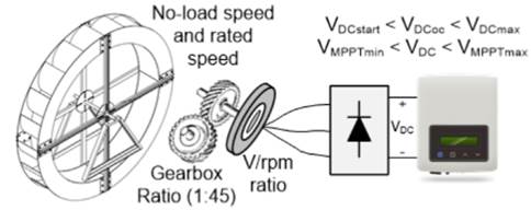
The methodology used in this work to connect the waterwheel to the utility grid is shown in Figure 3. It consists of a suitable integration of a PMSG and a PV inverter. This approach has been investigated over the last few years [25,26], including very small-scale hydro systems [25,26,28]. It is a viable alternative to the conventional way of connecting hydro generators to the grid [8,36]. In fact, with this approach, the PMSG does not need to operate at a constant speed, close to the rated speed, and its operating point can vary within a wide operating range. In this way, the use of complex mechanical devices to control the generator speed is avoided.
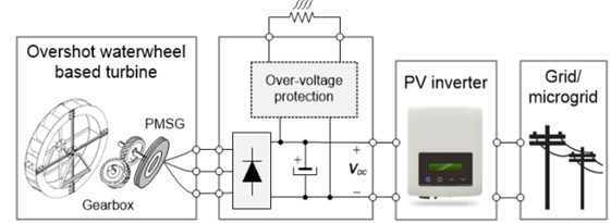
The first stage of power conversion in Figure 3 is from hydraulic (Equation (1)] to mechanical power, given by ω×T, where T is the torque (Nm) and ω is the waterwheel rotational speed (rad/s). Unfortunately, this speed is very low (≤ 20rpm) and operating speeds less than 10 rpm are expected [32,36]. Because of this drawback, a second mechanical power conversion stage is necessary, from low speed to higher speed (and lower torque). This is achieved through a high ratio gearbox, as illustrated in Figure 3. Even so, it may be necessary to use a low-speed PMSG, commonly used in small wind turbines. Indeed, from the calculator [34], the rotation speed of the waterwheel (6.8 rpm). This is very low, even for PMSGs used in low-speed wind turbines, where the speed is in the range of some hundreds of rpm. Because of this constraint, and to achieve a rotational speed of not less than 300 rpm, a gearbox available on the market, with a gear ratio of 1:45 was selected.
The generator performs the third conversion stage, converting the shaft’s mechanical power (ω × T) into AC electrical power, characterized by a three-phase voltage system. Next, a full-bridge rectifier converts these voltages into a DC voltage and current. After this fourth stage, the power (W) is given by P = Vd×Id, being Vd and Id the average values of voltage and current, respectively, at the output of the rectifier bridge.
Last but not least, a fifth conversion stage (DC to AC) is needed to perform the interface with the grid. For this purpose, there are three available approaches: developing specific power converters [8,25]; using wind turbine inverters; or using PV inverters [26]. The first requires a lot of development time, and several legal requirements must be accomplished. Even so, as with the second option, using wind inverters, the solution requires knowledge of the turbine’s power curve and the consequent parameterization of the inverter. The third approach is the most “plug and play” of all and is based on widely available PV string inverters [25] or microinverters [26] . Whichever the approach, an over-voltage protection circuit is most likely required [28], as illustrated in Figure 3.
Unfortunately, the third approach is not completely universal. The compatibility of the PV inverter with a pico-hydro turbine depends on the maximum power point tracking (MPPT) algorithm and mainly on the way it is initialized [38]. For the PV inverters to be compatible with a water turbine, it is still necessary to make compatible the operating point range of both: the generator (ω,T) and inverter (Vdc,Idc). Next section presents a more in-depth development of this compatibility.
3.2 Compatibility analysis
The set consisting of the PMSG and the full-bridge rectifier can be described as a single-stage conversion of the shaft mechanical power into the DC electrical power at the input of the inverter. From the perspective of this power conversion stage, it is important to analyse, in some detail, the relationship between the operating point at the input (on the generator shaft) and at the output of the full-bridge rectifier. Analysis of conversion from mechanical power to DC electrical power Figure 4 presents the three-phase steady-state equivalent circuit of a non-salient PMSG and diode rectifier followed by a DC source modeling the input stage of the PV inverter. Indeed, in most cases, for the pico-hydro power range, the input stage of the PV inverter consists of a DC/DC converter or a high-frequency DC/AC converter [39]. In addition to operating with an output voltage much higher than the input, this input stage makes the modules operate at their maximum power point (MPP).
From the point of view of its input, the PV inverter behaves like a dynamic resistor, adjusting the voltage (through the MPPT algorithm) in order to maximize the power and, therefore, maximize the current for the MPP voltage. In this way, it is possible to model the PV inverter (viewed from the input), as a current source[27] as shown in Figure 4, where X is the reactance due to stator winding (X s ) and line (X L ), R corresponds to the stator (R s ) and line (R L ) resistances, and Vs and Is are, respectively, the stator phase voltage and current of the non-salient PMSG. The induced electromotive voltage in the stator winding (E) is directly proportional to the electrical angular speed (rad/s). V d and I b are, respectively, the output DC voltage and current of the rectifier. The average output voltage of the three-phase full-bridge diode rectifier is given by Equation (3), where V d,o.c . is the DC open-circuit voltage, and △V d corresponds to voltage drop due to generator and line inductances (Ls + LL), resistances (Rs + RL) and across the diodes.
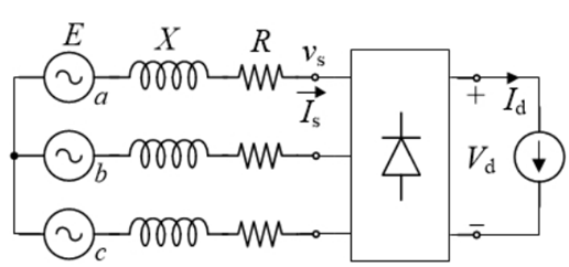
Figure 4 Steady-state equivalent circuit of PMSG, transmission line, diode rectifier and PV inverter

The first term of Equation (3) is given by Vd,o.c. = 3 π × √ 2VLL [40], being VLL the generator’s open circuit line-to-line voltage. Furthermore, VLL = √ 3E and the amplitude of the induced electromotive voltage, Em, is given by √ 2E. On the other hand, Em = kEω, being kE the generators’ speed constant. Therefore, the first term of Equation (3) can be replaced by Equation (4):
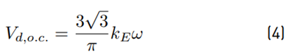
It is clear that V
d,o.c.
is directly proportional to the electrical angular speed, as shown by Equation (4). Due to the presence of the reactance X = X
s
+ X
L
, the current commutation from one diode to the other in the rectifier bridge, does not occur instantaneously. It takes a time interval and consequently, during this interval, two upper diodes (and one lower diode), or two lower diodes (and one upper diode) will conduct simultaneously. Thus, during this commutation interval, one of the line-to-line voltages is equal to zero, while the other two are equal to V
d
or −V
d
. Therefore, the second term in Equation (3), △V
d
, is equal to 3
 , provided that the voltage drop in the rectifier’s diodes and across the resistances (R
s
+R
L
) are neglected [27,40]. Thus, Equation (3) can be rewritten as shown in Equation (5):
, provided that the voltage drop in the rectifier’s diodes and across the resistances (R
s
+R
L
) are neglected [27,40]. Thus, Equation (3) can be rewritten as shown in Equation (5):
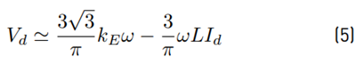
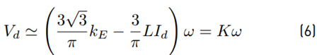
From Equation (5), it is clear that, for each operating point, the DC input voltage at the PV inverter is proportional to the generator’s rotational speed, as shown in Equation (6):
Another important relationship for the analysis of the compatibility between the operating point of the generator and the PV inverter is the relationship between the torque and the DC current at the output of the rectifier.
It is well known, from the control perspective, that torque is proportional to the stator current amplitude because the current space-phasor leads the rotor flux space-phasor by 90º, in order to maximize the torque [40].
Another perspective results from the dynamic modeling in the dq synchronous reference frame. In this case, the torque is proportional to the stator current quadrature component [27], which is supposed to be a DC current. Unfortunately, this relationship is not so straightforward [41]. Indeed, the nonlinearity caused by the full-bridge rectifier makes significant harmonics appear in the stator current, as well as in its quadrature component in the synchronous reference frame.
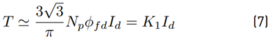
The relationship between the amplitude of the fundamental component of the generator current and the DC current at the output of the rectifier is
 , but the generator current also has harmonics of order 6k±1, k = 1, 2, 3, · [42]. The relationship between Is and Id has already been deepened in some works for the case where the generator is connected to a three-phase full bridge rectifier. For instance, [43] addresses the analysis with constant-voltage loads and [27] considers a constant DC load current. In the latter case, the load current is controlled by a boost converter to control the operating point of a wind turbine.
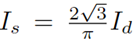
In the context of grid-connected pico-hydro systems, as illustrated in Figure 3, the commercial PV inverter does not expect to have a hydro-power source instead of a PV one, at the input side. Thus, what is known is that, from the input side, it behaves like a dynamic resistance, adjusted according to its MPPT algorithm, so that the operating point corresponds to the maximum power point. It is very likely that the frequency of this tuning is less than a few Hz [38]. On the other hand, the input current controller bandwidth is certainly much higher. Furthermore, the most common situation of PV inverters is to have a high inductance at the input power stage, e.g., the inductance of a boost converter [27]. For these reasons, the PV inverter was modeled as a current source, as shown in Figure 4 and hence the result of Equation (5). Under these conditions, the authors in [27] deduce, in some detail, the relationship between the torque and the current Id, as described in Equation (7):
where Np is the number of pole pares and ϕfd is the amplitude of the flux linkage in the stator winding due to permanent magnets in the rotor. Equation (7) shows that the electromagnetic torque is proportional to the DC output current of the rectifier. The same conclusion can be easily obtained by equating the generator’s shaft power to the rectifier’s DC output power, taking into account the efficiency (η g+r ) of both (generator+rectifier), i.e., η g+r × ω × T = V d × I d , and approximating V d by Equation (4) . Then, after some elementary manipulations, Equation (8) is obtained.
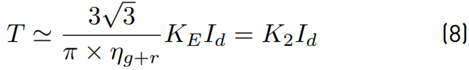
Knowing that E = kωϕ fd = KEω it follows that both Equations (7) and (8) are basically the same.
The next section presents the analysis of the compatibility of the DC power, at the output of the bridge rectifier, with the PV inverter.
Analysis of the compatibility of the DC power with the PV inverter
This section focuses on the analysis of the compatibility between the DC output power of the generator and the PV inverter input, in the context of Figure 3. Considering Equations (6) and (8), it results that the PV inverter controls the operating point of the waterwheel (turbine), i.e., the rotational speed and torque. This is accomplished by controlling, respectively, the voltage Vd and current I d at the output of the rectifier bridge. Furthermore, an additional goal was to find a “plug and play” approach to avoid the over-voltage protection circuit, as shown in Figure 5.
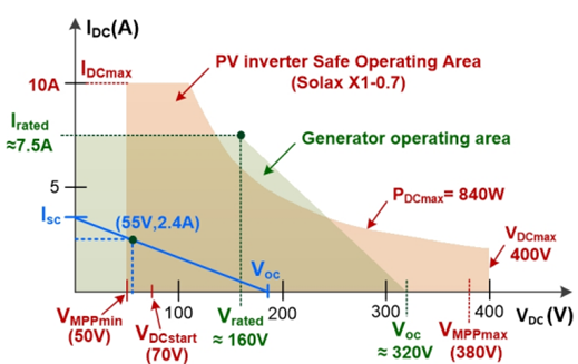
Generally speaking, the compatibility between the generator (and, therefore, the waterwheel) and the PV inverter consists of assuring that the operating points of both are inside a common area of their respective safe operating areas (SOAs). Figure 6 presents the SOAs of the Solax X1-0.7 PV inverter and 80-7s-2p PMSG, which were used in the implementation, as will be described in section 4.
The compatibility is ensured by sizing the operating point (IDC , VDC ), in a common zone of the generator and inverter operating areas, as illustrated in Figure 6. According to Figures 5 and 6, in order to ensure this requirement, it is necessary:
To determine the waterwheel rotational speed (in normal and no-load operation);
To select the gearbox ratio and the generator V /rpm constant;
To check whether, for the minimum water flow, the open circuit (no-load) voltage is higher than the minimum voltage necessary for the inverter to start operating (VDCoc > VDCstart);
To check that, for the maximum water flow, the voltage does not exceed the inverter’s maximum voltage (VDCoc < VDCmax);
And, finally, to confirm that the operating voltage, for the expected variations in head and water flow, is within the inverter’s MPPT range (VMP Pmin < VDC < VMP Pmax).
These requirements also apply to other turbines and PV inverters.
4. Implementation and experimental results
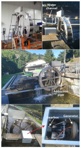
This section describes the on-site implementation of the constructed overshot waterwheel and the validation of the grid connection approach, as described in the previous section. Figure 7 shows the overshot waterwheel installed in the fish tank. The flow rate was measured indirectly by averaging several counts of the time it took a colored spot to travel through the inlet pipe. The flow rate obtained was about 13 l/s.
During the tests carried out over the first six months of 2021, at different times, the no-load rotational speed of the wheel varied between 22.5 and 25.5 rpm. The speed under load, around the maximum power, and for the flow available at each moment, varied between 7.8 and 12 rpm. For the initial design requirements, the expected operating speed was 6.8 rpm (with 25 l/s).
Taking into account the 1:45 speed ratio of the selected gearbox, the shaft speed of the generator is in the range 351 − 540 rpm. At no-load conditions, this speed reaches 1148 rpm. According to section 3.2, this speed must be higher enough to generate a DC voltage at the rectifier output, higher than the starting operating voltage of the PV inverter (V DCoc > V DCstart ). On the other hand, the rectifier’s output voltage should be sufficiently lower than the maximum value of the DC input voltage of the PV inverter (V DCoc < V DCmax ). Otherwise, the grid connection will not be completely “plug and play”, being necessary to use an over-voltage protection circuit [28]. Furthermore, the DC operating voltage, around the MPP of the turbine, must be within the MPPT voltage range of the PV inverter (V MP Pmin < VDC < V MP Pmax ). Therefore, a suitable rated voltage of the generator, or speed constant V/rpm, must be selected for a given PV inverter or, for a given inverter, the rated speed of the generator must be conveniently selected, together with the gearbox ratio.
In practice, the solution design is an iterative process and considers the equipment available on the market and its cost. Fortunately, for the power in question, new inverters are being launched on the market with a wide MPPT range, where the lower limit is getting smaller. For instance, from the datasheets of the Solax X1-0.6 and Solis-mini-700-4G PV inverters, it can be seen that the lower limit of the MPPT range is, respectively, 45 and 50 V. On the other hand, the maximum voltage of input is high enough, respectively 450 and 600 V, to make the over-voltage protection circuit unnecessary.
To connect the waterwheel to the utility grid, the Solax X1-0.7-S-D(L) inverter was purchased with maximum DC input power 840 W, maximum DC input voltage 400 V , MPPT voltage range 55 − 380 VDC and start operating voltage 70 V DC .
Additionally, tests were carried out with three different generators connected to the gearbox and waterwheel. The first was a low-speed axial flux permanent magnet generator, AFPMG260, designed for small wind turbines. The rated output power, speed, DC voltage and DC current are, respectively, 300 W, 300 rpm, 28 V DC , 10.71 A DC . The stator is star connected and the DC values refer to the output of the three-phase rectifier.
The second generator was a higher voltage PMSG, PGS 100R-WB 488, with the following rated characteristics: 800 W, 1500 rpm, 385 V AC , 1.25 AAC . This is a 100 Hz, 8 pole axial PMSG and these nameplate values are for star connection. In this work, the stator connections were reconfigured from star to delta to reduce the voltage.
The third generator is based on a three-phase BLDC (Brushless DC) electrical machine working as a permanent magnet alternator [44]. This is a lower-cost solution for small power applications. To operate as a generator, like the previous two, it is connected to a three-phase rectifier and the DC output voltage constant is 0.199 V /rpm (under no-load). It is based on a delta-connected 80-7s-2p stator with 42 poles and a rotor type 2 (0.75 W/rpm). According to [44], the rated output power, speed, DC voltage and DC current are, respectively, 1200 W, 1600 rpm, 180 V and 6.7 A.
The tests with generators AFPMG260, PGS 100R and 80-7s-2p were performed on site, respectively, on 21 December 2020, 23 February 2021 and 9 June 2021.
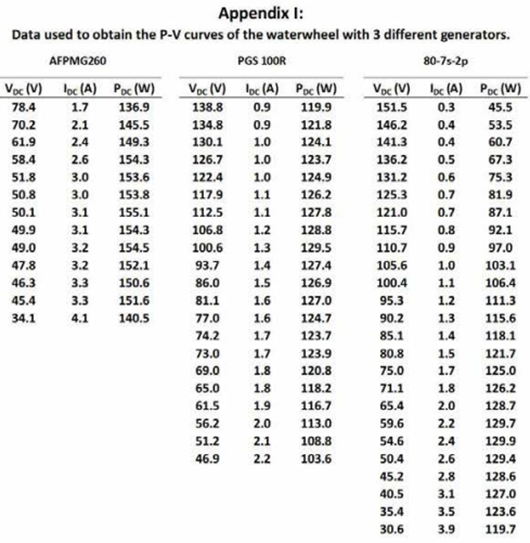
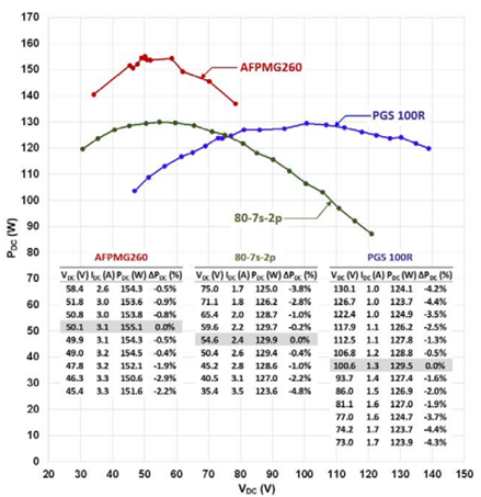
To identify the point of maximum power, for the available flow rate, the curves P DC versus V DC were obtained, through the variation of load resistance. The results are presented in Figure 8. This figure also presents the values of DC voltage and DC current for a power variation of less than 5%, around the MPP. The values of the voltages and currents presented in Figure 8, and used to calculate the DC power, correspond to the average of 3 to 5 readings.
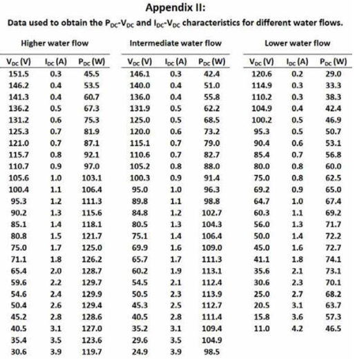
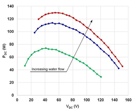
Figures 9 and 10 show the tracing of the DC power and current curves, respectively, as a function of DC voltage. The curves were obtained with the 80-7s-2p generator, for three different water flows. Figure 9 shows that the power curves have a well-defined MPP zone, and the voltage value corresponding to the MPP increases with the flow rate. It can be seen that the shape of the P DC − V DC curves is similar to the corresponding curves of a PV string. Figure 10 shows that the I DC −V DC curves have a very different shape to those obtained with a PV string.
Usually, T − ω curve is approximated by a straight line [45,46]. According to Equations (6) and (7) the relationship I − V should also be linear. However, Figures 9 and 10 show that neither the P − V curves are a perfect inverted parabola, nor the I − V curves are linear.
The waterwheel was connected to the grid using the PV inverter Solax X1-0.7, either with generator 80-7s-2p or generator PGS 100R. Unfortunately, the inverter was not yet available when the AFPMG260 generator was attached to the waterwheel.
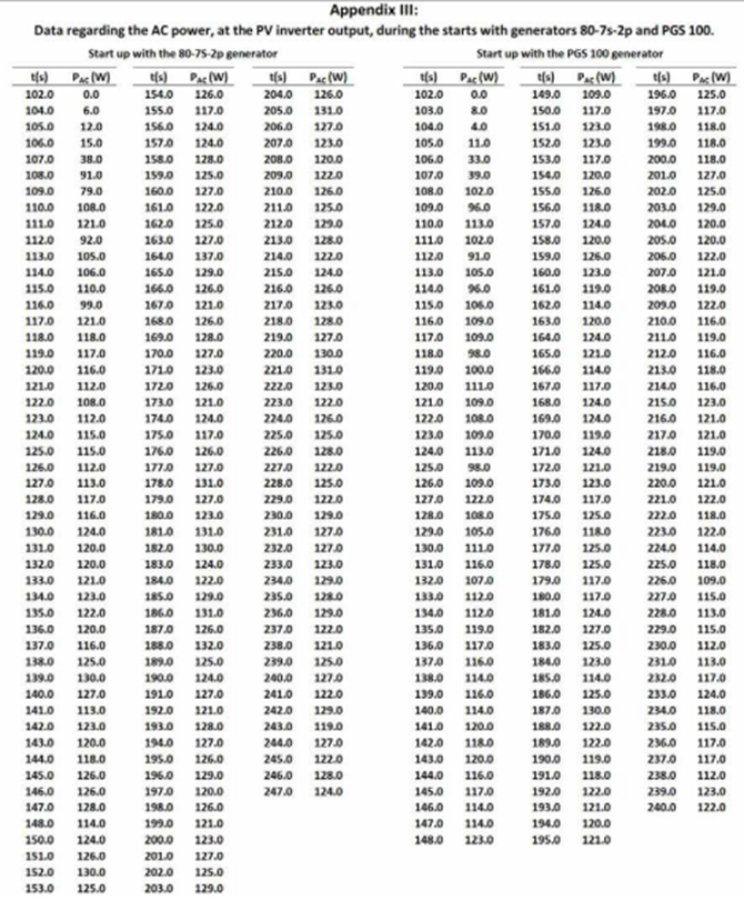
Figure 11 shows the first 4 minutes of the waterwheel connection to the grid. The maximum AC power obtained with the 80-7s-2p generator was 137 W and 130 W with generator PGS 100R. The average AC power, during the last minute, was 125.8 W and 119.6 W, respectively.
The waterwheel speed under no-load was 25 rpm, and under load operation, it was 9 rpm with generator 80-7s-2p and 11 rpm with generator PGS 100R. Obviously, due to the gearbox, the shaft speed of the generator is 45 times higher.
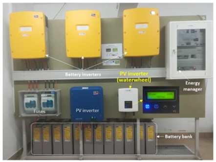
Actually, using the approach described in this work, the waterwheel was connected to a smart microgrid, as illustrated in Figure 12. The microgrid is based on the SMA Flexible Storage System with battery backup function and increased self-consumption [47]. It uses 3 bidirectional inverters (Sunny Island 6.0H) [48], in a master-slave configuration, which are connected to a 48 V, 625 Ah battery bank. The microgrid also integrates a 10 kWp PV system using the multi-string inverter STP10000TL-20. The energy management and power control are performed by the battery inverters and by an energy manager (Sunny Home Manager) [49]. The microgrid was installed under the Project BIOURB-NATUR and the implementation details are out of the scope of this work.
5. Analysis and discussion
Tests with the different generators were carried out at different times of the year and, most likely, with different flow rates. Without a water flow meter available on site, it is not possible to accurately relate the power to the water flow values, but this limitation does not compromise the objectives of the work. In fact, the most relevant data were accurately measured, namely DC power (by measuring DC current and DC voltage) and AC power, in steady-state and during grid connection. Thus, with the method used to measure the flow rate, it is not possible to accurately compare the DC power values obtained with the three generators shown in Figure 8.
As illustrated in Figure 5, by choosing a suitable gearbox ratio and a generator V /rpm constant, the operating DC voltage, at the output of the rectifier bridge, will be within the MPPT range of the PV inverter. Thus, the PV inverter will adjust its input voltage, through the MPPT algorithm, in order to extract the maximum power. On the other hand, if its maximum value, under no-load operation, is less than the maximum DC voltage at the inverter input, the over-voltage protection circuit can be avoided, as shown in Figure 5.
By analysing Figure 8, and considering a variation less than 5% around the MPP, it can be seen that the DC voltage range is 45.4 − 58.4 V, 73 − 130.1 V and 35.4 − 75 V for generators AFPMG260, PGS 100R and 80-7s-2p, respectively. Although the MPPT range on the nameplate of the PV inverter is 55 − 380 V, in practice, the lower limit is around 50 V. Thus, the inverter works close to the lower limit of its MPPT range with generators AFPMG260 and 80-7s-2p and inside the first quarter of the MPPT range with the generator PGS 100R.
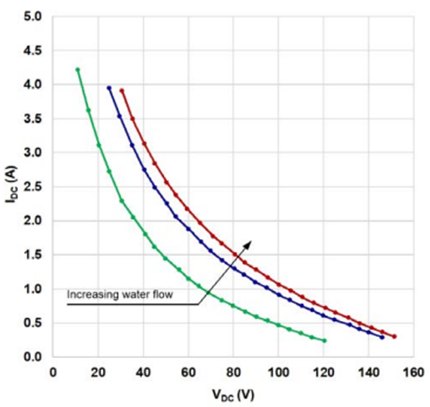
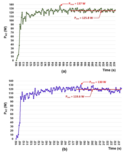
Figure 11 Grid connection of the overshot waterwheel using PV inverter Solax X1-0.7 and generators: (a) 80-7s-2p and (b) PGS 100
As illustrated in Figure 5, after the gearbox has been selected with a high transmission ratio (1:45 in this case), a generator with a suitable voltage constant (V /rpm) must be selected. In fact, there is a compromise: on the one hand, this constant must be large enough so that the voltage around the MPP is within the MPPT range of the inverter and, on the other hand, it must be small enough so that under no-load operation, the voltage does not exceed the upper limit of the inverter’s input voltage (400 V in this case). Otherwise, an over-voltage protection circuit would be required.
It must be taken into account that the voltage constant (V/rpm) of the generator on load can be significantly lower than its value under no-load operation. For example, for the 80-7s-2p generator, the value at maximum output power was expected to be in the range 55% − 60% of the value under no-load [44]. However, according to the tests carried out, it was about 31%.
Figure 11 shows the evolution of the AC power injected into the grid (at the inverter output) during a start-up with generators 80-7s-2p and PGS 100R. The Solax X1-0.7 inverter took about 100 seconds to start injecting power into the grid after switching ON the switch on the DC side. About 40 s later it reached the steady-state operation.
After that, it continued to extract power, oscillating around the MPP due to the voltage perturbation introduced by the MPPT algorithm of the inverter.
Before switching ON the input breaker of the PV inverter, the DC open-circuit voltage (V DCoc ) was approximately 186 V and 252 V with generators 80-7s-2p and PGS 100R, respectively. This means that an over-voltage protection circuit is not needed since the maximum input DC voltage of the PV inverter is 400 V . Figure 6 shows the overlap of the safe operating areas of Solax X1-0.7 PV inverter and 80-7s-2p generator that are installed on-site. The VDC operating voltage is about 55 V, just above the lower limit of the MPPT range (VMP Pmin). For the nominal water flow (25 l/s), this voltage would increase. In any case, the (no-load) output voltage constant of the generator should not be lower than 0.199 V /rpm. From Figure 6, the compatibility is ensured since the start operating voltage is V DCstart = 70 V DC , and the MPPT voltage range is 50-380 VDC. In addition, the maximum input voltage, V DCmax = 400 V, is sufficiently higher than V DCoc that the over-voltage protection circuit is not required.
6. Conclusions
This paper described the design of an effective grid connection approach for a pico-hydro system based on an overshot waterwheel. It is based on the integration of a permanent magnet synchronous generator and a photovoltaic (PV) inverter. Three generators and a conventional PV inverter were used for evaluation purposes. Following this approach, the waterwheel was connected to a microgrid and it is operating in an aquaculture centre, taking advantage of the waterfall in one of its tanks, with a head of 2 m and a flow rate of only about 13 l/s. This pico-hydro system injects 126 W into the grid, with a global efficiency of about 50%.
This work demonstrates how hydroelectric energy can be generated on a very small-scale, properly integrated into existing infrastructures and, therefore, without the need for any civil construction works. On the other hand, it demonstrates how the generated energy can be injected into the grid, in a simple and effective way, using only equipment widely available on the market.
For the connection to the utility grid, the generator’s three-phase voltage system is converted to a DC voltage. Then, a conventional PV inverter (through its MPPT algorithm) controls the operating point of the waterwheel, i.e., the rotational speed and torque, by controlling, respectively, the voltage (V DC ) and current (I DC ) at the output of the rectifier bridge.
This work also demonstrates that an additional over-voltage protection circuit can be dispensed by suitably selecting the gearbox ratio and generator’s constants W/rpm and V/rpm.
The compatibility between a pico-hydro turbine and the PV inverter was analysed in detail. The use of a PV inverter offers an effective (robust, flexible, efficient, economical, and “plug and play”) interface with the utility grid. It is believed that these results will be of the utmost importance for many companies installing distributed generation systems.
On the other hand, they may contribute to the widespread exploitation of small hydro resources untapped so far and without environmental impact. However, it should be emphasised that not all PV inverters may be compatible with hydro generation. The dynamics of the MPPT algorithm and especially the way it is initiated may make the use of some inverters unfeasible.